Hello! Welcome back to your course on radioelectronics.
In our last lesson, you were introduced to the powerful concept of the transfer function, . We derived it for a series RC circuit and saw preliminary evidence of its filtering capabilities by analyzing its behavior at frequency extremes. You correctly noted that it seemed to pass low frequencies while blocking high ones.
Introduction
Today's Goal: We will formalize that observation. This lesson focuses on defining and analyzing the RC Low-Pass Filter. You will learn precisely how to calculate its cutoff frequency, which is the critical threshold that separates the frequencies the filter passes from those it attenuates.
This concept is a cornerstone of signal processing. In your world of software engineering, you might think of a low-pass filter as being analogous to an exponential smoothing algorithm on a time-series dataset—it filters out high-frequency noise or "jitter" to reveal the underlying, slower-moving trend. By the end of this lesson, you will be able to derive, define, and graphically represent the key characteristics of this fundamental electronic circuit.
Time to complete: Approximately 45 minutes.
1. The Low-Pass Filter Transfer Function Revisited
Let's begin by solidifying our understanding of the RC circuit's transfer function. As a quick recap from our previous session, consider the standard series RC circuit where the output voltage is measured across the capacitor.
We use the voltage divider rule in the frequency domain to find the transfer function, . The following video provides an excellent and clear derivation, which will serve as a great review of the process.
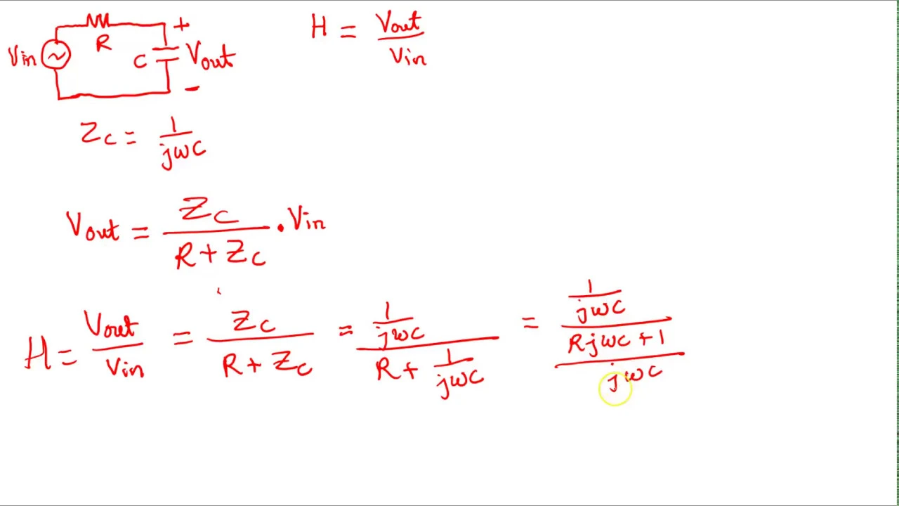
- Resource: by ENGRTUTOR
- Watch: 00:00 - 03:41 (Deriving the Transfer Function)
- Focus on: How the voltage divider rule is applied using the complex impedances for R and C ( and ).
As the video demonstrates, the derivation steps are:
- Apply Voltage Divider:
- Simplify Algebraically: Multiplying the numerator and denominator by gives us the standard form:
This single expression elegantly captures the circuit's entire frequency response.
2. Magnitude and Phase Analysis
Since the transfer function is a complex number, it has both a magnitude (gain) and a phase angle. Let's analyze these to understand how the circuit modifies a signal.
- Watch: 03:41 - 06:34 of the same video, .
- Focus on: The formulas used to extract the magnitude and phase from the complex expression.
The key formulas derived are:
- Magnitude (Gain): This tells us how much the signal's amplitude is scaled.
- Phase Angle: This tells us the phase shift between the output and input signals.
Now, let's use these equations to confirm the "low-pass" behavior you intuited in the last lesson.
- Watch: 06:34 - 10:03 of .
- Focus on: The analysis at the frequency extremes: DC () and very high frequency ().
Let's summarize this crucial analysis:
-
At DC ():
- Gain: . The circuit passes the signal with no reduction in amplitude.
- Phase: . There is no phase shift.
- Intuition: The capacitor's impedance goes to infinity, acting as an open circuit. No current flows, so there is no voltage drop across R, and .
-
At High Frequencies ():
- Gain: . The circuit heavily attenuates, or blocks, the signal.
- Phase: . The output lags the input by a quarter cycle.
- Intuition: The capacitor's impedance approaches zero, acting like a short circuit to ground. This effectively shunts the output signal to ground, making .
This behavior—passing low frequencies and blocking high ones—is the definition of a low-pass filter.
3. The Cutoff Frequency: Defining the Boundary
We've seen that the filter's gain changes from 1 to 0 as frequency increases. But where is the "boundary" between the frequencies that are "passed" and those that are "blocked"? This boundary is defined by the cutoff frequency, denoted (in rad/s) or (in Hz).
The cutoff frequency is formally defined as the frequency at which the output power has dropped to half of its maximum level in the passband.
Since power is proportional to voltage squared (), half power corresponds to the voltage magnitude dropping to of its maximum value.
This is also famously known as the -3dB point, a term you will see constantly in datasheets and engineering literature.
Let's watch the derivation of the formula for .
- Watch: 10:03 - 12:30 of .
- Focus on: The algebraic steps to solve for the frequency that makes the magnitude equal to .
To recap the derivation: we set the magnitude formula equal to and solve for :
Squaring both sides and solving gives:
This gives us the simple and elegant formula for the cutoff frequency in radians per second:
To express this in Hertz (cycles per second), we use the relationship :
This frequency is determined entirely by the values of the resistor and the capacitor.
4. Visualizing the Filter Response
A graph of the magnitude and phase versus frequency, often called a Bode plot, provides the most intuitive understanding of a filter's behavior.
- Watch: 12:30 - 14:59 of .
- Focus on: The shape of the magnitude and phase plots and how they visually represent the low-pass characteristic.
The key features of the low-pass filter's plots are:
-
Magnitude Plot:
- Passband: For , the gain is flat and close to 1 (or 0 dB).
- Cutoff Frequency (): The gain is exactly (or -3 dB).
- Stopband: For , the gain "rolls off," decreasing steadily as frequency increases.
-
Phase Plot:
- Starts at 0° for low frequencies.
- Passes through -45° exactly at the cutoff frequency .
- Approaches -90° at very high frequencies.
Conclusion
In this lesson, we formalized the identity and characteristics of the RC low-pass filter, a fundamental building block in electronics.
Key Takeaways:
- An RC circuit with the output taken across the capacitor functions as a low-pass filter.
- Its transfer function is .
- The cutoff frequency marks the -3dB point, where the filter's gain drops to (approx. 70.7%) of its maximum value.
- The passband is the range of frequencies below that are passed with minimal attenuation. The stopband is the range above that is progressively attenuated.
What's Next?
Now that you've mastered the low-pass filter, a natural question arises: what happens if we swap the positions of the resistor and capacitor? In the next lesson, we will do exactly that. You will analyze the circuit where the output is taken across the resistor and discover that this simple change creates a High-Pass RC Filter, a circuit with the opposite filtering characteristic.