Hello! Welcome to the final lesson in our module on AC circuit analysis.
In the last two lessons, you mastered the fundamentals of first-order filters. You learned how to build a low-pass filter by taking the output across a capacitor and a high-pass filter by taking it across a resistor. You can now derive their transfer functions and pinpoint their cutoff frequencies.
Introduction
Today's Goal: We will build directly on that knowledge to explore Band-Pass and Band-Stop Filter Concepts. What if you don't want to just pass all low or all high frequencies? What if you need to isolate a specific frequency range, like a single radio station, or remove a specific source of noise, like 50/60 Hz mains hum? This is where band-pass and band-stop filters are essential.
In this lesson, you will learn:
- The principles of band-pass filters, which pass a select band of frequencies.
- The principles of band-stop filters, which reject a select band of frequencies.
- How these can be constructed by combining the low-pass and high-pass filters we've already studied.
- Alternative RLC circuit topologies that achieve the same goal through the principle of resonance, a concept you'll be familiar with from your radiophysics background.
This lesson concludes our exploration of the frequency domain and sets the stage for our next module, where we will shift our focus to time-domain analysis.
Time to complete: Approximately 60 minutes.
1. The Band-Pass Filter
A band-pass filter allows a specific range of frequencies to pass through while attenuating frequencies both below and above that range.
1.1. Construction by Cascading Filters
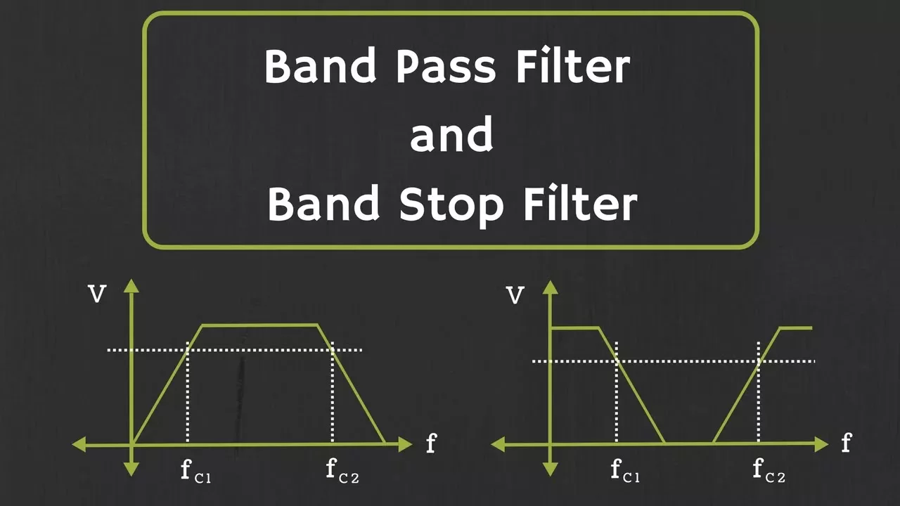
The most intuitive way to build a band-pass filter is to combine what we already know. If we pass a signal first through a high-pass filter and then through a low-pass filter, the result is a band-pass filter.
- The high-pass filter blocks frequencies below its cutoff, .
- The low-pass filter blocks frequencies above its cutoff, .
For this to work, we must ensure that . The overlapping passbands of the two filters create the passband for the final filter.
The following video segment explains this concept clearly.
- Resource: by ALL ABOUT ELECTRONICS
- Watch: 00:47 - 03:01 (Introduction to Band-Pass Filters)
- Focus on: How cascading a high-pass and a low-pass filter results in an overlapping region that defines the passband.
1.2. Key Parameters of a Band-Pass Filter
The frequency response of a band-pass filter is defined by a few key parameters:
- Lower Cutoff Frequency (): The -3dB point on the lower end, determined by the high-pass section.
- Higher Cutoff Frequency (): The -3dB point on the upper end, determined by the low-pass section.
- Bandwidth (BW): The width of the passband, calculated as .
- Center Frequency (): The frequency at the center of the passband. It is the geometric mean of the cutoff frequencies: . For many applications, especially with narrow bandwidths, it's often approximated as the arithmetic mean.
The video below quickly reviews these parameters and also introduces the phase response.
- Resource: by ALL ABOUT ELECTRONICS
- Watch: 03:01 - 04:02 (Band-Pass Filter Parameters and Phase Response)
- Focus on: The definitions of bandwidth and center frequency.
1.3. Example: Passive Cascaded Filter and its Limitation
Let's see how this works with a concrete example. The video calculates the bandwidth for a band-pass filter made from a passive RC high-pass filter followed by a passive RC low-pass filter.
Watch the following clip to see the calculation. Pay close attention to the discussion at the end about the "loading effect."
- Resource: by ALL ABOUT ELECTRONICS
- Watch: 04:02 - 07:46 (Example Calculation and Active Filters)
- Key points:
- The cutoff frequency for each stage is calculated independently using .
- The bandwidth is the difference between these two frequencies.
- Loading Effect: When connecting passive stages, the second stage draws current from the first, altering its behavior. The calculated cutoff frequencies are therefore only an approximation. To prevent this, a buffer (like an op-amp voltage follower) is often placed between stages to isolate them.
1.4. Alternative: RLC Resonant Filters
As you'll recall from your studies, RLC circuits exhibit resonance, a property that is perfect for creating frequency-selective filters.
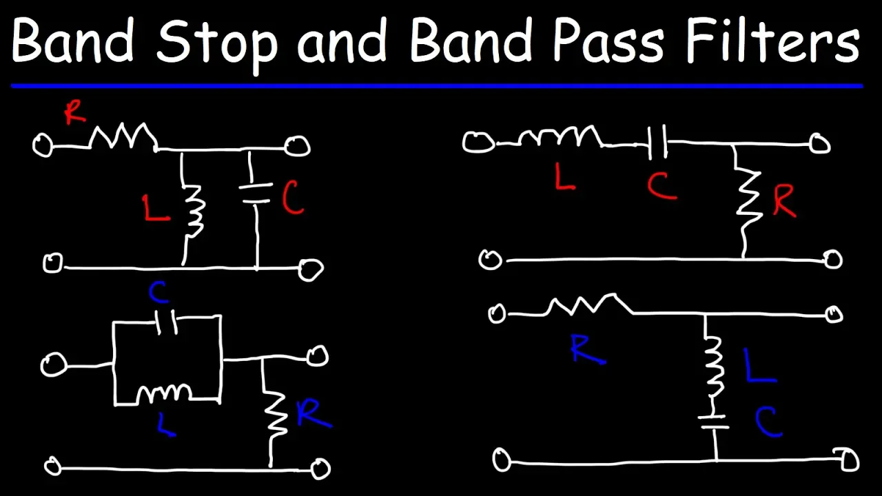
- A series RLC circuit has minimum impedance at its resonant frequency. If you take the output across the resistor, you create a voltage divider that maximally passes signals at resonance, thus acting as a band-pass filter.
- A parallel RLC (or LC tank) circuit has maximum impedance at resonance. If this is placed in series with an output resistor, it forms a voltage divider that again maximally passes signals at resonance, also forming a band-pass filter.
The following video illustrates these two classic band-pass topologies.
- Resource: by The Organic Chemistry Tutor
- Watch: 00:48 - 05:45 (Band-Pass Filter Concepts and RLC Circuits)
- Focus on: The intuition behind how the inductor (blocks high frequencies) and capacitor (blocks low frequencies) work together in both series and parallel configurations to pass only a band of mid-level frequencies.
2. The Band-Stop Filter
A band-stop filter (also known as a band-reject or notch filter) does the opposite of a band-pass filter: it rejects a specific band of frequencies while passing all others.
2.1. Construction by Summing Filters
Conceptually, a band-stop filter can be created by summing the outputs of a low-pass filter and a high-pass filter, where the low-pass cutoff is lower than the high-pass cutoff .
- The low-pass filter passes all frequencies up to .
- The high-pass filter passes all frequencies above .
- When added together, the only frequencies missing are those in the "notch" between and .
The video below explains this concept and shows how it can be implemented practically using an op-amp summing amplifier.
- Resource: by ALL ABOUT ELECTRONICS
- Watch: 07:46 - 10:06 (Introduction to Band-Stop Filters)
- Focus on: Understanding how the combined response of a low-pass and high-pass filter creates the band-stop characteristic, and seeing the op-amp circuit that realizes this summing function.
2.2. Alternative: RLC Resonant Filters
RLC circuits can also be configured as highly effective band-stop filters. The principle is the inverse of the band-pass case.
- A series LC circuit shunted across the signal path to ground will have minimum impedance at resonance. It will effectively "short out" signals at that specific frequency, creating a notch.
- A parallel LC tank circuit placed in series with the signal path will have maximum impedance at resonance, blocking signals at that frequency from reaching the output.
This next clip clearly demonstrates these two RLC band-stop configurations.
- Resource: by The Organic Chemistry Tutor
- Watch: 05:45 - 10:46 (Band-Stop Filter Concepts and RLC Circuits)
- Focus on: How the RLC components are arranged to either block mid-level frequencies or shunt them to ground, while allowing low and high frequencies to pass to the output.
Conclusion
In this lesson, you have seen how the fundamental building blocks of low-pass and high-pass filters can be combined to create more complex and useful frequency responses.
Key Takeaways:
- Band-Pass Filters pass a specific range of frequencies. They can be conceptually built by cascading a high-pass and a low-pass filter or implemented using RLC resonant circuits.
- Band-Stop Filters reject a specific range of frequencies. They can be conceptually built by summing the outputs of a low-pass and a high-pass filter or implemented using RLC resonant circuits.
- The key parameters for both filter types are the lower and higher cutoff frequencies (, ), the bandwidth (), and the center frequency ().
- Cascading passive filters suffers from loading effects, which can be mitigated using active components like op-amp buffers.
What's Next?
This lesson concludes our module on AC circuit analysis in the frequency domain. We have focused on the "steady-state" response of circuits to sinusoidal inputs of different frequencies.
In the next module, "Time-Domain Analysis and Transient Response," we will shift our perspective. We will analyze what happens in the moments immediately after a switch is thrown or a signal source is suddenly applied. This involves deriving and solving the ordinary differential equations (ODEs) that govern circuit behavior, bringing us to the heart of the advanced mathematical analysis you are aiming for.