
Hello! Welcome to your next lesson on fluid dynamics.
In our last session, we used the linear momentum equation to calculate the total force a moving fluid exerts on objects like pipe bends and jet engines. We saw that this force is a direct result of the fluid changing its momentum.
Today, we will focus on what happens when a body is completely immersed in a moving fluid, like an airplane wing in the air or a submarine in the water. We'll decompose the total fluid force into two critical components that are fundamental to aerospace engineering: lift and drag. Your learning outcome for this lesson is to analyze flow around immersed bodies using drag and lift coefficients.
By the end of this lesson, you will understand where lift and drag come from and how to use dimensionless coefficients to calculate their magnitude—a core skill for any aspiring aerospace engineer.
1. From Total Force to Lift and Drag
When a fluid flows over a body, it exerts forces on the body's surface. As we saw in the last lesson, these forces arise from two sources:
- Pressure distribution acting perpendicular to the surface.
- Wall shear stress (friction) acting parallel to the surface.
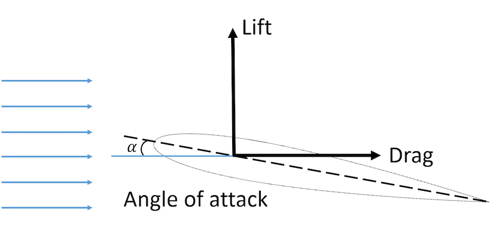
Integrating these pressure and shear stress distributions over the entire surface gives the resultant force, , on the body. For engineering purposes, especially in aerospace, it's far more useful to resolve this resultant force into two components relative to the direction of the oncoming fluid flow (the free-stream velocity, ):
- Drag (): The component of the force parallel to the direction of the upstream flow. It represents the fluid's resistance to the body's motion.
- Lift (): The component of the force perpendicular to the direction of the upstream flow.
2. The Origins of Drag
The drag force itself is also composed of two parts, corresponding to its physical origins:
- Pressure Drag (or Form Drag): Caused by the pressure difference between the front and rear of the body. This is dominant for blunt, non-streamlined bodies where the flow separates from the surface, creating a low-pressure wake region behind the body.
- Friction Drag (or Skin Friction Drag): Caused by the shear stress of the fluid "rubbing" against the body's surface. This is the dominant form of drag for highly streamlined bodies like an airfoil at a small angle of attack.
The following video provides an excellent visual explanation of these concepts.
Understanding Aerodynamic Drag
The video 'Understanding Aerodynamic Drag' by The Efficient Engineer clearly explains the fundamental concepts of drag. Pay close attention to how it breaks down drag into its pressure and friction components.
Watch the video from the beginning to 8:01. Focus on these key points: 0:00 - 2:31: The definitions of lift and drag, and the introduction of pressure drag and friction drag. 2:31 - 5:22: How pressure drag is created by flow separation and an adverse pressure gradient. Notice the examples of the golf ball and vortex generators, which use turbulence to delay separation and reduce drag. 5:22 - 8:01: How friction drag dominates for streamlined bodies and the opposite effect turbulence has on it compared to pressure drag. See how streamlining involves a trade-off between these two types of drag.
3. The Drag and Lift Equations
Calculating lift and drag by integrating pressure and shear stress is extremely difficult. Instead, we use a practical engineering approach based on dimensionless numbers, which you've already seen with the Reynolds number and friction factor. Here, we introduce the drag coefficient () and the lift coefficient ().
The drag and lift forces are calculated using these simple and powerful equations:
Drag Equation:
Lift Equation:
Let's break down the terms:
- and : The drag and lift coefficients. These are dimensionless numbers that depend on the body's shape, its orientation (angle of attack), and the flow regime (i.e., the Reynolds Number). They are typically determined experimentally in a wind tunnel or through computational fluid dynamics (CFD).
- : The density of the fluid.
- : The free-stream velocity of the fluid.
- : This group of terms is called the dynamic pressure, representing the kinetic energy per unit volume of the fluid.
- : A characteristic reference area. The choice of reference area is critical and must be specified. For bluff bodies like spheres or cars, it is typically the frontal area (the projected area you see from the front). For streamlined bodies like wings, it is the planform area (the area you see from above).
The formal definitions are provided in the following reading.
Notes on Thermodynamics, Fluid Mechanics, and Gas ...
The document 'Notes on Thermodynamics, Fluid Mechanics, and Gas...' from Purdue University provides the formal definitions for the lift and drag coefficients and their reference areas.
Read the section defining the lift and drag coefficients. It starts after the figures for streamlined and bluff bodies and is marked as note (3). This will formalize the equations we just introduced and clarify the concept of frontal vs. planform area (see Figure 9.28).
4. Factors Affecting Lift and Drag Coefficients
The values of and are not constant. They are primarily influenced by the body's shape, its angle of attack, and the Reynolds number of the flow.
The Effect of Reynolds Number and Shape on Drag
For a given shape, the drag coefficient changes with the Reynolds number (). This is because the Reynolds number dictates the nature of the boundary layer (laminar or turbulent), which in turn affects flow separation.
Drag coefficient as a function of Reynolds number for a smooth sphere and cylinder. Note the sudden drop, known as the "drag crisis," where the boundary layer becomes turbulent, delaying flow separation and drastically reducing pressure drag. This chart is similar to Figure 9.35 in the Purdue notes.
As you saw in the video, a turbulent boundary layer has more energy and can resist flow separation longer than a laminar one. This is why golf balls have dimples—to trigger turbulence, delay separation, and lower the pressure drag.
The document below provides tables of typical drag coefficients for various common shapes, which are invaluable for quick engineering estimates.
Notes on Thermodynamics, Fluid Mechanics, and Gas ...
Let's return to the Purdue notes to see some typical drag coefficient values.
Briefly look over Figures 9.37 and 9.38. You don't need to memorize them, but appreciate the wide variation in C_D based on geometry. Notice how a streamlined shape has a much lower C_D than a blunt one, like a flat plate.
Test your understanding!
A car travels at 90 km/h. It has a frontal area of 2.5 m². The drag coefficient is . An engineer proposes a modification that reduces the drag coefficient to . What is the reduction in drag force? (Assume the density of air is kg/m³).
Show answer
First, convert the velocity to m/s:
Next, calculate the initial drag force:
Then, calculate the new drag force:
The reduction in drag force is:
This 10% reduction in results in a force reduction of about 28.7 N. While this may seem small, remember that the power needed to overcome drag is , so this directly translates to improved fuel efficiency.
The Effect of Angle of Attack on Lift
For lift-generating bodies like airfoils, the most important factor is the angle of attack ().
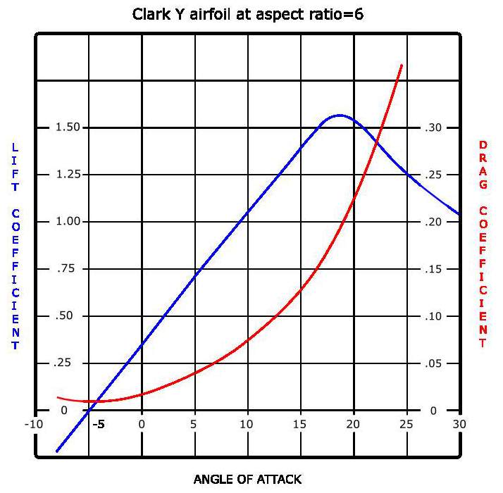
As you can see from the graph:
- The lift coefficient (, blue line) increases almost linearly with the angle of attack up to a certain point.
- At a critical angle of attack (around 14-16° here), the flow separates abruptly from the top surface of the wing. This causes to drop sharply, a dangerous condition known as stall.
- The drag coefficient (, red line) is low at small angles but increases dramatically as the wing approaches stall.
The video below explains how lift is generated and how devices like flaps are used to increase lift during takeoff and landing.
Understanding Aerodynamic Lift
Now let's watch 'Understanding Aerodynamic Lift' from The Efficient Engineer. It provides an intuitive explanation for how airfoils generate lift and the critical concept of stall.
Watch the segments from 0:47 to 2:34 and 10:17 to 12:03. Focus on: 0:47 - 2:34: The key terminology of an airfoil (chord line, camber, angle of attack). 10:17 - 12:03: The phenomenon of stall and how high-lift devices like flaps work by changing the airfoil's shape to increase its camber.
5. Worked Example: Force on a Car Spoiler
Let's apply these concepts to a simple aerospace-related problem: calculating the downforce from a car's rear spoiler, which is essentially an inverted airfoil.
Notes on Thermodynamics, Fluid Mechanics, and Gas ...
The following example from the Purdue notes calculates the downforce (a negative lift) produced by a car spoiler. It's a great demonstration of applying the lift equation.
Read the example 'liftdrag_07' on page 1009. Follow the steps to see how the lift equation is used with a given lift coefficient to find the force. Note the comment about how much speed is needed to generate a significant force, which is why these devices are most effective in racing.
Conclusion
In this lesson, we've explored the crucial concepts of lift and drag, which are central to analyzing the motion of vehicles through fluids. You now have the tools to quantify these forces, a foundational skill for your aerospace engineering goals.
Key Takeaways:
- Lift and drag are the components of the total aerodynamic force acting perpendicular and parallel to the fluid flow, respectively.
- Drag is comprised of pressure drag (due to shape and flow separation) and friction drag (due to surface shear stress).
- Lift and drag are calculated using the lift and drag equations, which rely on the dimensionless coefficients and .
- These coefficients are not constant; they depend on the body's shape, its orientation (angle of attack), and the Reynolds number of the flow.
- Stall is a critical flight condition where an increase in the angle of attack leads to a sudden loss of lift.
Preview of the Next Module:
We have now concluded our module on fluid flow applications. We've seen how to analyze energy in pipe systems and how to calculate forces on immersed bodies.
Now, we will pivot to the first module in Dynamics. In our next lesson, we will step back from forces and focus on Kinematics—the pure geometry of motion. We'll learn to apply kinematic equations to solve problems of particle motion, developing the mathematical language to describe velocity and acceleration. This will build the foundation for later connecting forces (like lift and drag) to the motion they produce, via Newton's Second Law.
Can't find a good explanation? Sign up and we'll make it for you
Sign up