
Welcome back. In the previous lesson, you established a traceable PSS®E workspace and distinguished source data from saved working cases. Now you will use that workspace to create the network skeleton of the WSCC/P.M. Anderson IEEE 9-bus system: its buses and six transmission-line records.
This is deliberately not yet a solvable power-flow case. The three generator buses will remain disconnected from the 230 kV network until you add their generator step-up transformers in the next lesson; generators and loads also come next. That separation is useful: it prevents a common modeling mistake in which a transformer connection is accidentally represented as a transmission line simply to make a one-line look connected.
By the end of this lesson, you should have a saved PSS®E case containing the nine correctly numbered buses, their base-kV levels, and the six correctly connected 230 kV transmission lines.
First, fix the version of the “IEEE 9-bus case” you are building
“IEEE 9-bus” is often used loosely. Several published versions have small differences in dispatch, limits, model conventions, and file format. For this course, use the conventional WSCC 3-machine, 9-bus / P.M. Anderson version with:
- 9 buses;
- 3 generator terminal buses;
- 3 two-winding generator step-up transformers;
- 6 transmission lines; and
- 3 loads.
The 100 MVA system base is customary for this version. Record that choice in your manifest before entering data.
Alroomi Website - 9-Bus System
Read the Alroomi Website’s overview and inspect its one-line diagrams. Use it to establish the equipment count and the distinction between the low-voltage generator buses and the 230 kV transmission network.
In “I. Introduction,” read the short description beginning the system overview. Then go to “II. Single-Line Diagram” and inspect one of the diagrams, tracing each connection before entering anything in PSS®E. Notice that the system has three voltage levels at generator terminals and one 230 kV transmission level.
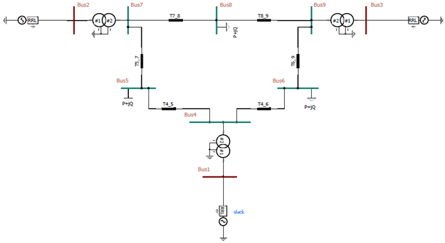
The diagram below is a useful independent visual check. It depicts the whole eventual system, including equipment you will add later. For this lesson, focus only on buses and the six paths between buses 4 through 9.
Read the topology as a network, not as a drawing
A one-line diagram is convenient, but the PSS®E model ultimately consists of records. Before opening the bus-data dialog, translate the visual diagram into an explicit connectivity list.
Bus records
Use the following bus numbering and nominal voltage levels.
| Bus | Suggested name | Base kV | Physical role in the completed system |
|---|---|---|---|
| 1 | BUS1 | 16.5 | Generator 1 terminal bus |
| 2 | BUS2 | 18.0 | Generator 2 terminal bus |
| 3 | BUS3 | 13.8 | Generator 3 terminal bus |
| 4 | BUS4 | 230.0 | Transmission-side bus for Generator 1 step-up transformer |
| 5 | BUS5 | 230.0 | Load-area transmission bus |
| 6 | BUS6 | 230.0 | Load-area transmission bus |
| 7 | BUS7 | 230.0 | Transmission-side bus for Generator 2 step-up transformer |
| 8 | BUS8 | 230.0 | Transmission junction bus |
| 9 | BUS9 | 230.0 | Transmission-side bus for Generator 3 step-up transformer |
The base-kV field is not merely descriptive. PSS®E uses it in network data, reporting, and consistency checks. A 230 kV transmission bus accidentally entered as 23 kV may not immediately look wrong in a text table, but it can corrupt later per-unit conversions and fault-study interpretation.
Transmission-line connectivity
The six transmission lines are all on the 230 kV network:
| Line | From bus | To bus | Circuit ID |
|---|---|---|---|
| L45 | 4 | 5 | 1 |
| L46 | 4 | 6 | 1 |
| L57 | 5 | 7 | 1 |
| L69 | 6 | 9 | 1 |
| L78 | 7 | 8 | 1 |
| L89 | 8 | 9 | 1 |
The six lines form a closed transmission loop:
- Bus 4 connects to buses 5 and 6.
- Bus 5 connects to buses 4 and 7.
- Bus 6 connects to buses 4 and 9.
- Bus 7 connects to buses 5 and 8.
- Bus 8 connects to buses 7 and 9.
- Bus 9 connects to buses 6 and 8.
There is no direct line from bus 5 to bus 6, bus 7 to bus 9, or bus 4 to bus 8. Those are easy errors to make if you enter records from memory rather than from a connectivity table.
Connections intentionally deferred
Three physical connections appear on the full one-line but should not be created as line records today:
| Future transformer | Low-voltage side | High-voltage side |
|---|---|---|
| Generator 1 step-up transformer | Bus 1, 16.5 kV | Bus 4, 230 kV |
| Generator 2 step-up transformer | Bus 2, 18.0 kV | Bus 7, 230 kV |
| Generator 3 step-up transformer | Bus 3, 13.8 kV | Bus 9, 230 kV |
These are two-winding transformers, not ordinary branches. Their turns ratio, impedance base, tap treatment, winding connection, and control options belong in transformer records. You will add them next lesson.
At the end of this lesson, buses 1, 2, and 3 are therefore expected to be electrically isolated. That is an intentional intermediate condition, not a topology error.
The minimum branch data needed for this build
A PSS®E transmission-line record includes more than its terminal buses. Even when your immediate objective is topology, the record needs series impedance and shunt charging data.
For the conventional 100 MVA P.M. Anderson version, enter the following as the initial transmission-line data:
| From | To | Circuit | p.u. | p.u. | Total p.u. |
|---|---|---|---|---|---|
| 4 | 5 | 1 | 0.0100 | 0.0850 | 0.1760 |
| 4 | 6 | 1 | 0.0170 | 0.0920 | 0.1580 |
| 5 | 7 | 1 | 0.0320 | 0.1610 | 0.3060 |
| 6 | 9 | 1 | 0.0390 | 0.1700 | 0.3580 |
| 7 | 8 | 1 | 0.0085 | 0.0720 | 0.1490 |
| 8 | 9 | 1 | 0.0119 | 0.1008 | 0.2090 |
Two details deserve care:
-
Circuit ID: use
1for every line because no parallel circuits exist in this test system. In a large utility model, the circuit ID distinguishes multiple branches having the same terminal buses. -
Line charging: PSS®E’s branch field uses the total line charging susceptance . Some published 9-bus tables show , meaning the shunt charging placed at each end of the nominal pi model. If the source lists , double it before entering total in the PSS®E branch record.
For example, the 4–5 line has p.u. at each end, so the total PSS®E branch charging entry is:
You will examine per-unit bases, thermal ratings, and sign conventions systematically in a later lesson. At this stage, enter the values consistently and preserve the source transcription in your project documentation.
Build the case in PSS®E
Menu names vary somewhat by PSS®E release, but the workflow is consistent: create a blank power-flow case, enter bus records, then enter branch records.
1. Create the case and record its identity
In your workspace:
- Create a build note such as
IEEE9_topology_build_notes.md. - Record the source as the P.M. Anderson/WSCC 9-bus version, the 100 MVA system base, and today’s date.
- Open a new or empty PSS®E power-flow case.
- Set the system MVA base to 100 MVA.
- Save an initial working file as:
IEEE9_TOPO_R00.sav
Do not call it BASE yet. It is not a complete base case, because it lacks transformers, generators, loads, and a valid power-flow solution.
2. Enter the nine buses
Open the Bus Data entry view in the power-flow network-data interface. Add buses 1 through 9 using the numbers, names, and base-kV values from the bus table.
For this deliberately incomplete stage, set all buses to the ordinary load-bus or PQ classification if PSS®E requires a bus type during entry. The classification is a power-flow control designation, not an inherent physical property of the bus.
In the completed case:
- bus 1 will become the swing bus;
- buses 2 and 3 will become generator-controlled PV buses; and
- buses 4 through 9 will be PQ buses.
Do not create fictitious generators merely to assign PV or swing status today. The actual generator records will establish these roles in the next lesson.
Use default area, zone, and owner fields only if your blank-case setup requires them. Record those defaults in your notes rather than assigning invented study meaning to them.
3. Enter the six 230 kV line records
Open the Branch Data or Non-Transformer Branch Data entry view. Enter the six rows from the transmission-line table.
For each line, check the following before accepting the record:
- the from-bus and to-bus numbers match the connectivity table;
- circuit ID is
1; - branch status is in service;
- , , and total have been entered in per unit on the stated 100 MVA base;
- you have not used a transformer data form for these six 230 kV lines; and
- you have not created line records 1–4, 2–7, or 3–9.
If the branch-entry view requires thermal ratings, do not invent them. Retain a blank or zero rating only if permitted by your PSS®E version, and mark the ratings as incomplete in the build note. A zero or unspecified rate should never be interpreted later as an actual unlimited facility rating.
4. Save the topology milestone
Save the case again under the same controlled name, or increment the revision if you corrected an entry:
IEEE9_TOPO_R00.sav
Then add a concise manifest entry:
| Manifest field | Example entry |
|---|---|
| Case ID | IEEE9_TOPO_R00 |
| Parent case | New empty PSS®E power-flow case |
| System base | 100 MVA |
| Buses entered | 1 through 9 |
| Lines entered | 4–5, 4–6, 5–7, 6–9, 7–8, 8–9 |
| Deferred equipment | Three transformers, three machines, three loads |
| Intended status | Topology-only; not valid for power-flow solution |
Verify the topology before trying to solve anything
At this point, do not run an AC power flow. The case is intentionally incomplete and has no connected swing source, generation, or load.
Instead, inspect the network data and, if convenient, create a simple PSS®E one-line layout for visual review. The review goal is structural rather than electrical.
Expected intermediate state
You should observe:
| Check | Expected result |
|---|---|
| Number of buses | 9 |
| Generator-terminal voltage levels | 16.5 kV at bus 1, 18 kV at bus 2, 13.8 kV at bus 3 |
| Transmission-bus voltage levels | 230 kV at buses 4–9 |
| Non-transformer branches | 6 |
| Connected transmission core | One six-bus loop containing buses 4–9 |
| Isolated buses | 1, 2, and 3, until transformers are added |
| Parallel circuits | None |
| Direct 4–7, 5–6, or 7–9 lines | None |
A valuable habit for larger cases is to count equipment in two ways:
- by records, using reports or data tables; and
- by topology, tracing the connections on a one-line.
If the counts disagree, stop and resolve the difference before studying results. A topology error in a nine-bus model is visible; the same error in a 100,000-bus planning case may survive unnoticed until it changes a contingency result.
Frequent modeling errors and their consequences
| Error | Why it happens | Later consequence |
|---|---|---|
| Modeling 1–4, 2–7, or 3–9 as lines | The physical connection is visible, but the equipment type is overlooked | Wrong voltage transformation and incorrect future fault or control behavior |
| Entering half charging as total | Source tables often show | Incorrect reactive-power balance and bus voltages |
| Using the wrong base kV at a generator bus | Bus labels are copied without voltage data | Incorrect transformer ratio and per-unit interpretation |
| Omitting one side of the six-line loop | Data are entered from memory | Artificially weak or radial transmission network |
| Creating a non-existent cross connection | A one-line is read too quickly | Altered flows, voltages, and contingency outcomes |
| Running a load flow now | A desire to “test” the case too early | Non-convergence is expected but can be misdiagnosed as bad line data |
Why this small topology exercise matters for interconnection studies
The IEEE 9-bus case is too small to represent an SPP cluster area, an ERCOT weak-grid pocket, or a WECC path assessment. It has no realistic geographic diversity, generator fleet, protection system, commitment logic, seasonal dispatch, or credible set of parallel transmission alternatives.
But the discipline transfers directly.
For example, when adding a solar-plus-BESS project to an authorized cluster model, you must distinguish:
- inverter terminals from collector buses;
- collector equivalents from generator step-up transformers;
- the high-side substation bus from the POI;
- existing transmission circuits from proposed upgrades; and
- a physical connection from the specific PSS®E record type that represents it.
A line modeled as a transformer, or a transformer modeled as a line, is not a small clerical defect. It changes voltage bases, losses, reactive behavior, fault paths, and possibly dynamic-controller measurement locations. The nine-bus case gives you a compact environment in which to build the correct record-level instincts.
Key takeaways
You have translated the P.M. Anderson IEEE 9-bus one-line into a controlled PSS®E topology:
- nine buses with correct numbers and nominal voltage levels;
- six 230 kV non-transformer branches;
- a closed transmission loop among buses 4 through 9; and
- three intentionally deferred transformer connections between buses 1–4, 2–7, and 3–9.
The current SAV is a topology milestone, not a solvable base case. Its isolated generator-terminal buses are expected until you add the three two-winding transformers, three generators, and three loads.
Next, you will add those transformer, generator, and load records to turn this skeleton into a complete steady-state network.
Can't find a good explanation? Sign up and we'll make it for you
Sign up