
Welcome back. You have already identified the campaign-checkout initiative’s main architecture drivers: payment correctness and recovery, peak checkout responsiveness, customer-specific order-status access, support diagnosis, and future sales-channel integration.
Now you will turn that information into a system-context diagram: the highest-level architectural view of the case study. It deliberately treats the system as a black box so that stakeholders can agree on scope, users, external dependencies, and important unanswered questions before the discussion turns into Spring Boot services, databases, queues, or Kubernetes.
Plan for roughly 45 minutes, including a short reading/video and a drafting pass.
The context diagram: a boundary, not an implementation
A system-context diagram answers a deceptively simple question:
What is the system we are responsible for, and what outside people and systems does it depend on or serve?
In C4 terminology, this is the Level 1: System Context view. It is like beginning with a map of a city rather than a floor plan of a building. The map shows where the system sits in its environment; later diagrams zoom into the applications, data stores, and components inside it.
Visualising software architecture with the C4 model - Simon Brown, Agile on the Beach 2019
Watch Simon Brown’s Visualising software architecture with the C4 model on the Agile on the Beach channel. It gives a concise explanation of C4’s zoom levels, then focuses specifically on what belongs in a Level 1 System Context diagram.
Watch the C4 overview to establish the four levels. Then watch Level 1 context, focusing on the three element types: the system in scope, people who use it, and external software systems it interacts with. Stop before the container-level discussion begins.
A context diagram is not a deployment diagram, a process flow, or a database diagram. Its central box should be one software system with a clear purpose. Everything outside that box is either:
- a person who uses or operates the system; or
- an external software system that exchanges information with it.
The lines show meaningful relationships, usually oriented from the initiator to the dependency. A line label should read naturally as a short action:
- “Customer submits checkout and views order status”
- “Support agent investigates uncertain orders”
- “Checkout system submits payment requests”
- “Sales channel creates checkout requests”
The arrow does not need to show every request and response packet. For example, a payment provider clearly returns a result after the checkout system calls it; adding a reverse “response” arrow usually adds clutter without clarifying responsibility.
Create architecture design diagrams - Azure
Read Microsoft Azure Well-Architected’s guidance on diagram quality and its definition of a context diagram. The first part will help you make the diagram usable in a review; the second establishes the deliberate black-box scope of this view.
In “Diagramming practices,” read the diagramming practices. Focus especially on directional arrows, clear relationship labels, consistency, progressive disclosure, and version control. Then, under “Types of design diagrams” in the “Context diagram” subsection, read the context definition. Notice that internal structure is intentionally excluded.
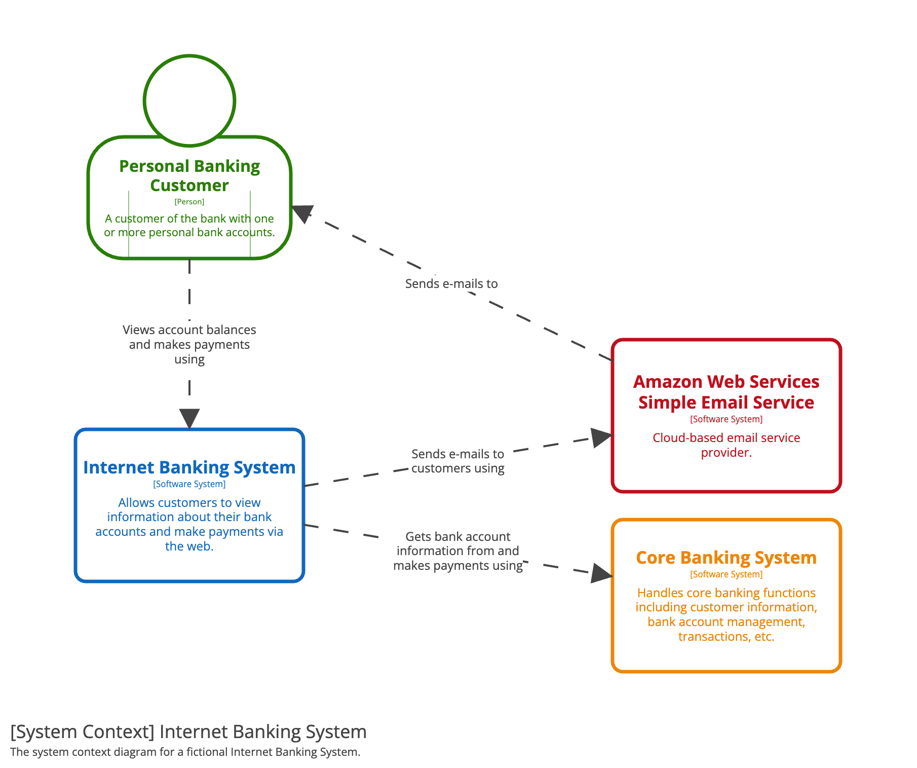
The fictional banking example below follows this principle: one banking system is the focus, while the customer, email service, and core banking system remain outside its boundary.
Decide the system boundary before drawing boxes
For this case study, use the following working scope statement:
Campaign Checkout System: enables campaign customers and integrated sales channels to submit checkout requests, obtain an unambiguous order outcome, and view order status; it coordinates payment processing but does not itself provide payment processing.
This sentence makes a consequential scope decision:
- The Campaign Checkout System owns the campaign checkout capability.
- The Payment Provider remains external, even though payment correctness is one of the most important requirements.
- Sales channels are external clients of the checkout capability, rather than internal modules of it.
- Customer-facing order status is within the system’s responsibility, but the identity and authorization mechanism is not yet assumed.
A system boundary is not simply “the repository our team currently owns.” For architecture framing, it is the boundary of responsibility being discussed. If a new checkout platform is being proposed, put that platform in scope even if it will later be implemented by multiple teams.
Your previous driver register tells you what must be visible at this level.
| Prioritized driver | Context-diagram consequence |
|---|---|
| Payment recovery is | Show the Payment Provider explicitly as an external dependency. Label the relationship to include reconciliation of uncertain outcomes, not merely “payment.” |
| Peak checkout responsiveness is | Do not add load balancers, caches, or databases here. Instead, preserve the driver as a note or link to the requirements brief. |
| Customers must access only their own status | Show the Customer and the checkout-status interaction. Record the source of identity as an open question if unknown. |
| Support diagnosis is | Show the Support Agent as a distinct operational persona, rather than treating support as an invisible internal activity. |
| Future sales-channel extensibility is | Show sales channels as external systems using the checkout capability. |
This is an important discipline: architecture drivers influence the context diagram, but they do not become boxes in it. “Performance,” “security,” and “availability” are properties the system must achieve, not external actors.
What belongs in this diagram—and what does not
At this level, omitting detail is a feature, not a deficiency.
| Include | Leave for later diagrams |
|---|---|
| One system in scope and its purpose | Spring Boot applications, modules, or microservices |
| Customers, support staff, and other meaningful personas | Controllers, service classes, or domain objects |
| External systems with a real business or technical dependency | PostgreSQL, Redis, Kafka, or internal queues |
| High-level relationship labels | REST endpoints, topic names, schemas, or database tables |
| Explicit system boundary and stated assumptions | Retries, timeouts, circuit breakers, and failure sequences |
| Relevant external trust or data dependencies | Pods, clusters, subnets, load balancers, and cloud regions |
For example, it would be premature to draw separate Order Service, Payment Orchestrator, Notification Service, and Order Database boxes. Those may become useful at the next C4 level—the container diagram—but they would make the current diagram answer the wrong question.
Likewise, do not add an Identity Provider merely because authorization is a priority. The requirement tells you that customers must not access one another’s order status. It does not yet establish whether identity comes from a sales channel, a central identity platform, or an authentication capability within the eventual checkout system. Record that as an unknown rather than presenting a guess as architecture fact.
Build the Campaign Checkout System context diagram
Start with the central system, then work outward.
1. Place the system in scope at the center
Use a business-oriented name and description:
- Name: Campaign Checkout System
- Type: Software system
- Purpose: Supports campaign checkout, payment outcome handling, and customer order-status access.
Avoid implementation names such as “checkout-api,” “payment-service,” or “orders-db.” Those names make the diagram prematurely reflect a solution rather than the problem boundary.
2. Add the people
The current case has two useful personas:
- Customer — submits checkout and views their own order status.
- Support Agent — investigates an uncertain order without needing an engineer to manually inspect logs or databases.
The distinction matters. The customer represents the critical revenue journey; the support agent represents the operational recovery journey. Combining them into an abstract “User” would erase a driver that has already been prioritized.
3. Add external systems
At minimum, the case currently establishes:
- Payment Provider — processes payment requests and must support, or at least be investigated for, safe reconciliation after uncertain outcomes.
- Existing and future Sales Channels — systems that create checkout requests and retrieve customer-visible status through an integration contract.
The label “existing and future” is intentional. The context diagram should communicate that sales-channel compatibility is a boundary concern without deciding how the API will be versioned. API versioning belongs in a later lesson.
4. Draw one-way, labelled relationships
The resulting draft looks like this:
Read each arrow aloud from source to target. It should form a concise statement that is both understandable and architecturally meaningful:
- “A customer submits checkout and views their own order status using the Campaign Checkout System.”
- “A support agent investigates uncertain order status using the Campaign Checkout System.”
- “The Campaign Checkout System submits payment requests and reconciles uncertain outcomes using the Payment Provider.”
The diagram does not claim that these are single HTTP calls, synchronous interactions, or final API contracts. It states the meaningful dependency and responsibility boundary.
Make assumptions and unknowns visible
A Staff-level diagram is not persuasive because it looks polished; it is useful because readers can distinguish facts, working assumptions, and unanswered questions.
For this initial draft, attach a compact note beside the diagram or in its accompanying architecture brief.
Working assumptions
- Existing and future sales channels are outside the Campaign Checkout System boundary.
- The Campaign Checkout System directly supports the customer checkout and order-status capability, even when a sales channel provides the customer interface.
- Payment processing is delegated to an external Payment Provider.
- Support agents require a bounded, authorized view of uncertain order state.
Open questions to validate
- Does the Payment Provider support idempotency keys for retrying payment requests?
- Can the provider be queried to reconcile a payment after a timeout or lost response?
- Which system authenticates the customer and provides the identity used for order-status authorization?
- Do sales channels receive status synchronously, asynchronously, or through both mechanisms?
- Is customer notification, such as email or SMS, part of this initiative’s scope or delegated to an existing platform?
Do not place every open question in the diagram itself. That would make the view unreadable. Put a small “assumptions and open questions” panel beneath it, or link the diagram to the driver register. The diagram remains a map; the notes explain the uncertain terrain.
One scope ambiguity deserves special attention. If discovery reveals that customers only interact through independently owned sales channels, revise the customer relationship to:
If the checkout system presents a directly owned customer experience as well as an integration API, retaining the direct Customer-to-System relationship is appropriate. Resolve this with product and channel stakeholders rather than drawing both possibilities merely to avoid a decision.
A disciplined drafting and review pass
Use the following short workflow to produce version of the diagram.
- Write the scope sentence first. If the team cannot agree on what the system does and does not own, stop there. Diagramming cannot repair an unresolved boundary.
- Extract nouns from the case narrative. Classify each one as system in scope, person, external software system, or an unresolved item. “Payment provider” is external; “payment retry” is behavior, not a box.
- Add only relationships that matter to the initiative. A relationship should explain an important dependency, user interaction, trust boundary, or operational responsibility.
- Label arrows with verbs and business meaning. Prefer “reconciles uncertain outcomes” to “REST API call.”
- Remove internal detail. If an item will be implemented by your own team inside the Campaign Checkout System, it belongs in the next zoom level, not here.
- Record assumptions and version the source. Give the diagram a title, author, date, version, and a link to the requirements or architecture brief. Store the Mermaid, C4 DSL, or diagram source beside the project documentation—not only as an exported image.
Before sharing it, conduct a quick review against these statements:
- The system in scope is visually unmistakable.
- Every other box is either a person or an external software system.
- Every line has a direction and a readable relationship label.
- The diagram can be understood without knowledge of Java, Spring Boot, or the proposed deployment environment.
- The Payment Provider, sales channels, customer, and support role are visible because the prioritized drivers justify their presence.
- Unknowns are recorded explicitly rather than hidden inside confident-looking boxes.
Key takeaways
A system-context diagram is the first architectural map of an initiative. It shows one black-box system in its environment, the people who interact with it, external systems it depends on, and the high-level relationships among them.
For the campaign-checkout case, the key context elements are the Customer, Support Agent, Sales Channels, Payment Provider, and the Campaign Checkout System boundary. Payment recovery, authorization, support diagnosis, and channel extensibility determine what must be visible; they do not yet determine services, databases, or technologies.
Your next lesson will turn this diagram and its accompanying assumptions into a one-page architecture brief. That brief will make the system’s goals, exclusions, constraints, assumptions, and open questions reviewable by both technical and business stakeholders.
Can't find a good explanation? Sign up and we'll make it for you
Sign up