
Hello! Welcome to the final lesson of our module on electromagnetic induction.
In our previous lessons, we established that a changing magnetic flux induces an EMF, as described by Faraday's Law, . We also explored Lenz's Law, which explains that the direction of the induced current always opposes the change in flux, a direct consequence of the conservation of energy.
So far, we've focused on scenarios where the magnetic field itself changes. Today, we will investigate the case where the magnetic field is constant, but a conductor moves through it. This gives rise to what is called motional EMF.
Our goal in this lesson is to calculate motional EMF and to show how this phenomenon can be understood from two equivalent perspectives:
- The microscopic action of the Lorentz force on charges within the moving conductor.
- The macroscopic view of Faraday's Law, where the flux changes because the area of the circuit changes.
By the end of this lesson, you will see that these are not two different effects, but rather two ways of describing the same fundamental principle, unifying the concepts we've covered.
1. The Microscopic View: Lorentz Force on Charges
Let's begin by considering a simple conducting rod of length moving with a constant velocity through a uniform magnetic field , which is directed into the page.
A conductor contains mobile charge carriers (electrons). Since these charges are moving along with the rod, they experience a magnetic force described by the Lorentz force law, .
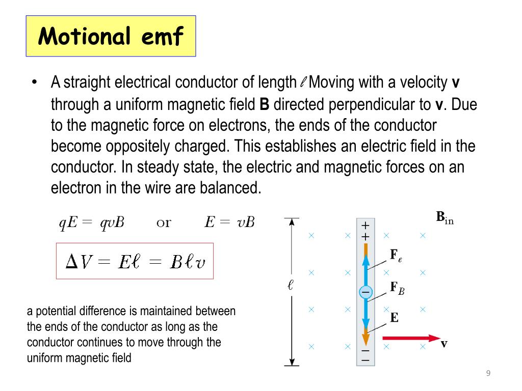
For an electron with charge , moving to the right, the right-hand rule indicates a downward magnetic force (). This force pushes the free electrons toward the lower end of the rod, leaving a net positive charge at the upper end.
This separation of charge creates an internal electric field pointing downwards, which in turn exerts an upward electric force on the remaining electrons. The charge separation continues until the system reaches equilibrium, where the magnetic and electric forces on the electrons balance each other perfectly:
This induced electric field creates a potential difference between the ends of the rod. This potential difference is the motional EMF (). For a uniform field over a length , this is simply:
This is the fundamental equation for motional EMF. It arises directly from the magnetic force on moving charges.
The following video provides an excellent derivation of this result and explores its consequences.
The video 'Motional EMF' by Physics Ninja clearly explains this derivation from the Lorentz force perspective. It then connects this EMF to an induced current and analyzes the forces and energy involved.
Please watch the segment from 01:44 to 06:37. This part focuses on deriving the motional EMF equation \mathcal{E} = BLv by considering the equilibrium of forces on an electron within the moving conductor.
2. The Macroscopic View: A Special Case of Faraday's Law
Now, let's analyze the same situation using Faraday's Law. Imagine our moving rod is now part of a closed circuit, sliding along a U-shaped rail as shown in many of the examples.
The magnetic flux through the loop is given by , where is the area of the loop. If the rod is at a position along the rails, the area is . The flux is therefore:
According to Faraday's Law, the induced EMF is the rate of change of this flux. Since and are constant, the change in flux is due entirely to the change in position :
Recognizing that the velocity of the rod is , the magnitude of the EMF is:
This is exactly the same result we derived from the Lorentz force! This confirms that motional EMF is not a new phenomenon, but rather a specific application of Faraday's Law where the flux changes due to motion (i.e., changing area).
The video you just watched also demonstrates this equivalence.
Let's continue with the 'Motional EMF' video to see how the Faraday's Law approach yields the same result.
Now watch the segment from 14:28 to 17:51. This section explicitly derives the motional EMF using Faraday's law by considering the rate of change of the loop's area, showing it's equivalent to the Lorentz force method.
3. Energy Conservation: Where Does the Energy Come From?
This is a crucial point that ties back to your goal of understanding electricity in terms of work done. If the sliding rod is part of a complete circuit with resistance , the motional EMF will drive a current .
Now, we have a current-carrying conductor of length moving in a magnetic field. This conductor will experience a magnetic force, .
- Using the right-hand rule for the direction of the current (which you can find using Lenz's Law from our previous lesson), you will find that this magnetic force opposes the motion of the rod. This is Lenz's law in action.
The magnitude of this "magnetic drag" force is:
To keep the rod moving at a constant velocity , an external agent must apply a force equal in magnitude and opposite in direction to this drag force, .
The mechanical power supplied by this external agent is the rate at which it does work:
Now, let's look at the electrical power dissipated as heat in the resistor:
The two expressions are identical. This beautifully demonstrates the principle of conservation of energy: the mechanical power you put in to move the rod is converted into electrical power in the circuit.
The following section of the video walks through this energy balance calculation.
This final segment of the 'Motional EMF' video explicitly calculates the applied force needed to maintain motion and demonstrates the conservation of power.
Please watch from 06:37 to 14:28. Pay close attention to the calculation of the magnetic drag force and the final comparison between mechanical input power and electrical dissipated power.
4. Worked Problem
Let's apply these concepts to a slightly more complex problem. The following example from the MIT course notes involves a sliding bar connected to two resistors in parallel, which requires you to combine motional EMF with the circuit analysis rules from our first module.
Chapter 10 Faraday's Law of Induction
Please read through the solved problem 'Sliding Rod' in the MIT notes on 'Faraday's Law of Induction'. It's a great example of applying the \mathcal{E}=BLv formula and then using Ohm's law for a parallel circuit.
Find and study the solution for problem '10.10.3 Sliding Rod' (page 10-25). Focus on how the single motional EMF is calculated first, and then how that EMF acts as a voltage source for the two parallel resistors.
Test your understanding!
A conducting bar of length m is fixed at one end and rotates with a constant angular velocity rad/s in a plane perpendicular to a uniform magnetic field T. What is the magnitude of the EMF induced between the two ends of the bar?
Hint: Not all parts of the bar move at the same speed. Consider a small segment of the bar at a distance from the pivot. The linear velocity of this segment is . Calculate the small EMF induced across this segment and then integrate from to .
Show answer
The EMF induced across a small segment at a distance from the pivot is given by the motional EMF formula, where the velocity is :
To find the total EMF across the entire length of the rod, we integrate this expression from the pivot () to the other end ():
Since and are constants, we can take them out of the integral:
Now, we can substitute the given values:
The induced EMF is 0.125 Volts. This rotating bar is the simplest form of an electric generator, a topic we will explore in detail later.
Conclusion
This lesson completes our study of electromagnetic induction by focusing on motional EMF. We have unified two different viewpoints—the microscopic Lorentz force and the macroscopic Faraday's Law—to show they produce the same result.
Key Takeaways:
- A conductor of length moving at velocity perpendicular to a magnetic field develops a motional EMF of .
- This can be understood as the potential difference arising from charge separation caused by the Lorentz force on charge carriers inside the conductor.
- It can also be understood as a specific case of Faraday's Law, where the magnetic flux changes because the area of a circuit is changing.
- The induced current creates a magnetic drag force that opposes the motion, requiring an external agent to do work.
- The mechanical power supplied by the external agent is converted into electrical power, satisfying the conservation of energy.
Preview of the Next Module:
We have now covered the foundational laws of static electric fields (Gauss's Law), static magnetic fields (Ampère's Law), and induction (Faraday's Law). In the next module, "Unification: Maxwell's Equations and EM Waves," we will assemble these pieces into a single, comprehensive theory of electromagnetism. Our first lesson will introduce the four famous equations of James Clerk Maxwell, which represent one of the greatest achievements in the history of physics.
Can't find a good explanation? Sign up and we'll make it for you
Sign up