
Hello. In the previous lesson, you estimated cooling time and saw that cooling rises roughly with the square of wall thickness. That result turns wall thickness into a design decision with direct consequences for cycle time, tooling cost, shrinkage, and part quality.
This lesson develops a practical method for choosing a nominal wall thickness—the primary, repeated thickness of a molded shell—and for handling the cases where wall thickness genuinely must change. You will use the 3:1 transition guideline to convert an abrupt step into a dimensioned, reviewable CAD feature. This is foundational for all three assumed EDV components: the ECU housing, door carrier, and HVAC outlet.
Uniform wall thickness is the starting point, not an aesthetic preference
Molten polymer fills the cavity, then cools and shrinks. A thin region loses heat quickly; a thick region remains hot and continues shrinking later. When those regions are connected, they constrain one another. The usual results are some combination of:
- sink marks, where a thicker internal region pulls the visible surface inward;
- warpage, where uneven contraction bends the part;
- voids within heavy sections;
- inconsistent dimensions, residual stress, or cosmetic variation;
- unnecessarily long cooling and cycle times.
A sound rule is therefore:
Use one nominal wall thickness across the main shell wherever the part’s function allows it. Treat every thicker or thinner region as an intentional exception that needs a functional reason and a DFM review.
The nominal wall is not necessarily the thickest measurement anywhere on the part. It is the baseline from which you design the enclosure, carrier, duct, bezel, or vane. Ribs, bosses, local seals, attachment features, and transitions are secondary features and should not accidentally become heavy thermal masses.
The 10 Commandments of Injection Molding
Watch “The 10 Commandments of Injection Molding” by EastWestMfg for a compact explanation of why uniform walls, properly proportioned ribs, and rounded changes work together.
Watch uniform walls to connect local thickness to shrinkage, cosmetic quality, and cooling time. Then watch ribs and bosses and abrupt changes. Focus on the central design logic: add stiffness efficiently with secondary features rather than making the whole shell thicker.
A supplier’s material-grade data sheet and mold-flow evidence ultimately govern the final design. The ranges in general DFM guides are useful screening limits, not release criteria for a specific automotive grade, tool, gate layout, and process window.
Injection Molding Wall Thickness Guidelines - Protolabs
Read Protolabs’ wall-thickness guidance to establish a reliable baseline before applying the 3:1 rule. It usefully connects nominal-wall selection with material choice, feature proportions, coring, and supplier DFM feedback.
In the opening section, read the uniform-wall rationale, then review the bulleted design guidance directly below it. In the subsection “Choose Materials with Wall Thickness in Mind,” study the material chart and context; use it only as an initial material-family screen. Finally, in “Frequently Asked Questions,” read the practical uniformity guidance, especially the distinction between a main wall and a secondary feature.
Selecting a nominal thickness: a controlled engineering decision
Do not begin with “What wall thickness is common?” Begin with: What thickness allows this material, geometry, process, and function to work together?
A useful selection sequence has five parts.
1. Start with the selected material grade
Use the material supplier’s recommended processing limits as the first boundary. Material family alone is insufficient. For example, two PA66 grades may have very different behavior because one is unfilled and another is glass-filled; a flame-retardant package, recycled content, impact modification, or moisture condition can also change flow and shrinkage behavior.
Record:
- material family and proposed commercial grade;
- supplier-recommended minimum and preferred wall range;
- shrinkage data and fiber orientation concerns, where applicable;
- relevant environmental conditions, such as temperature, chemical exposure, UV exposure, or moisture;
- whether the material selection is preliminary or approved.
For this course, the wall thickness decision belongs in the same controlled record as the material decision matrix. If the material changes, the wall decision must be reviewed rather than silently carried forward.
2. Check flow length, gates, and thin regions
A wall can satisfy a generic material chart but still be impractical if molten polymer must travel too far from the gate, negotiate restrictive turns, or fill several branches before reaching an end-of-fill region. Thin walls also raise required injection pressure—the connection to the clamp-force screening calculation from the previous lesson.
At this early stage, document:
- the longest likely flow path from the proposed gate;
- the thinnest primary wall;
- any end-of-fill regions;
- whether a single gate, multiple gates, hot runner, or cold runner is assumed;
- the confidence level of the assessment.
Later, mold-flow analysis will test whether the chosen thickness, gate strategy, and process window are viable.
3. Check structural and packaging function
The wall must support the intended function. Examples include:
- An ECU housing needs sufficient stiffness for mounting loads, gasket compression, fastener loads, connector retention, and handling, while maintaining electrical clearances.
- A door carrier needs stiffness over large spans, attachment load paths, and controlled surface quality, but it should obtain much of that stiffness through ribs and geometry rather than a uniformly massive wall.
- An HVAC outlet needs stable duct and bezel geometry, but its thin internal blades and mechanism clearances may impose different local constraints.
Do not use thickness alone to solve a stiffness problem. Increasing wall thickness adds mass and thermal mass throughout the part. A rib, gusset, flange, return, bead, or locally altered section can often put material where it contributes more effectively.
4. Check appearance and dimensional risk
A visible Class-A surface has little tolerance for sink, read-through, or waviness. A non-visible B-side may accommodate carefully designed reinforcement, but its thermal effect still reaches the show surface.
The strongest early question is:
If this region becomes thicker, where does the extra heat go, and what surface or functional datum lies opposite it?
5. Check cooling and production cost
The prior lesson’s one-dimensional cooling model gives a useful directional comparison. If a nominal wall changes from to , the approximate relative cooling-time change is:
All else equal, the thicker section can require about 56 percent more cooling time. The actual cycle-time effect depends on the full part, tool cooling, and process, but the calculation is enough to challenge unnecessary thickening early.
Use a nominal-wall target and an exception map
For a preliminary concept, select one nominal wall and create a visible map of exceptions. A useful screening convention is to keep the main shell near the nominal thickness, with a rough variation band of plus or minus 25 percent unless a reviewed transition or functional feature requires otherwise:
This is a practical DFM screen, not a universal standard or a substitute for supplier approval.
Suppose an assumed enclosure material grade supports a preliminary range that includes , and early packaging plus stiffness reasoning support that choice. Then:
The initial main-wall screening band is:
That does not mean every feature must lie within this range. A rib may intentionally be thinner, and a local sealing region may need carefully reviewed geometry. It means that a heavy zone in an otherwise housing should trigger a design review, not be treated as harmless.
At each exception, identify one of four dispositions:
| Exception type | Preferred response |
|---|---|
| Stiffness needed over a span | Use ribs, gussets, beads, returns, or section geometry |
| Thick solid volume is present | Core it where function and tooling permit |
| Change in shell thickness is unavoidable | Use a gradual 3:1 transition |
| Thin region is needed for package or flexibility | Check filling, local strength, draft, and assembly robustness |
The Cored Geometry image shows why coring is often preferable to a bulky solid form. In the left examples, the thicker block and T-shaped intersection create local thermal masses; the middle examples show the likely sink and warpage response. The cored alternatives preserve a more consistent material thickness.
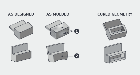
Coring is not simply “hollow it out.” It must preserve structural load paths, required sealing or attachment faces, tooling access, radii, and ejection feasibility. Nonetheless, it is usually the first redesign option when a thick region exists merely because the CAD began as a solid block.
The 3:1 transition guideline
Perfect uniformity is not always possible. A housing may need a thinner perimeter flange, a duct may need to blend into a restricted package, or a local functional interface may impose a different wall. When this occurs, do not create a sharp step.
The standard screening guideline is:
where:
| Quantity | Meaning |
|---|---|
| Wall thickness on the thick side | |
| Wall thickness on the thin side | |
| Axial length available for a gradual taper, chamfer, or radiused blend |
Read 3:1 as three units of transition length for every one unit of thickness change. It is not three times the thinner wall thickness, and it is not an arbitrary fillet radius.
For a transition from to :
A CAD drawing or section should therefore show a transition length of at least . If packaging permits more length, a longer, smoother transition is generally preferable.
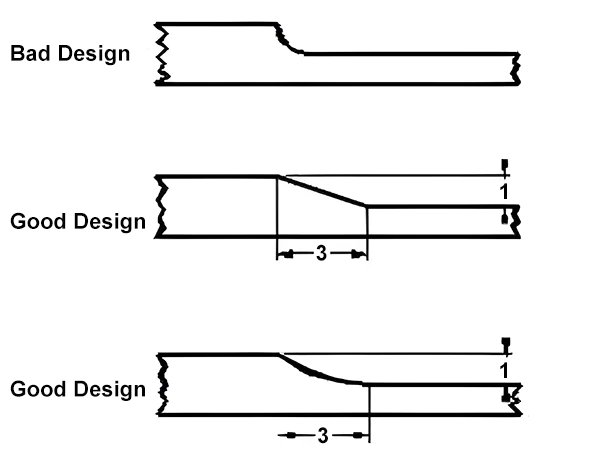
The material can transition using either of these approaches:
- a linear taper or chamfer, which is direct to dimension and often easy to inspect;
- a radiused blend, which can distribute stress smoothly and may better suit surface continuity.
Whichever method you choose, measure the meaningful length along the direction of the thickness change. A tiny cosmetic fillet at the edge of a sharp step is not a 3:1 transition.
Injection Molding Design Tips (avoid common defects)
Watch the short “Injection Molding Design Tips (avoid common defects)” segment by Protolabs for a visual statement of the gradual-transition rule.
Watch the transition rule. Notice that the recommended chamfer or fillet span is tied to the difference between the two wall thicknesses, while the purpose is to reduce warpage risk during solidification.
What the 3:1 rule solves—and what it does not
A gradual transition improves melt flow and reduces the geometric shock caused by an abrupt step. It also reduces local residual stress and makes the change less likely to telegraph as a cosmetic defect.
However, it does not make a large thick zone thermally equivalent to a thin one. A gradual ramp from to still contains a region with long cooling time and elevated sink or void risk. The ramp may be correctly proportioned:
but the more important question remains: Why is the section needed?
Before accepting such a transition, try these design changes:
- Core the thick region from the nonfunctional side.
- Replace bulk with thin ribs, gussets, or a boxed section.
- Move the load path closer to existing walls or mounts.
- Split the function across two components if assembly and cost permit.
- Reconsider the gate strategy and seek supplier mold-flow input if the geometry is unavoidable.
This distinction is especially important for a door-trim carrier. A transition can prevent a sharp wall step, but it will not prevent Class-A sink if a thick doghouse, rib root, or reinforcement sits directly behind a visible surface.
CAD intent: make the rule inspectable
For the projects in this course, do not leave wall decisions as implicit geometry. Make them inspectable and revision-controlled.
In an Onshape Part Studio, a practical concept workflow is:
- Establish a variable or clearly recorded dimension for the nominal wall thickness.
- Build the principal shell from that value rather than assigning unrelated thicknesses feature by feature.
- Create section views through every major thickness change, boss root, rib root, flange, and attachment zone.
- Measure the two wall values and the length of each transition.
- Add a note or a sketch dimension showing the 3:1 calculation at each intentional exception.
- Save a named version before a major DFM change, then record why the nominal thickness or transition was changed.
In CATIA, the corresponding intent is to control shell or thickness features with parameters, preserve stable reference geometry, and use sectioning or thickness-analysis tools to inspect the result. The exact command sequence differs across CATIA V5, 3DEXPERIENCE CATIA, and your available Onshape workflow; the engineering evidence should not differ.
For each part, create a Wall Thickness and Transition Record containing:
| Field | Example |
|---|---|
| Record ID | DFM-WALL-ECU-001 |
| Part and revision | ECU base, concept revision A |
| Material status | Proposed grade; supplier data pending |
| Nominal wall | |
| Main-wall variation screen | to |
| Thickness exceptions | Sealing flange, connector region, mounting interface |
| Transition evidence | Section view, thicknesses, calculated minimum length, actual modeled length |
| Thick-section treatment | Cored, ribbed, retained with justification, or open issue |
| Linked evidence | Cooling estimate, material matrix, supplier DFM, mold-flow result |
| Maturity | Concept, reviewed, supplier-approved, or superseded |
| Change traceability | Onshape version and ECO or change-register reference |
This record will become valuable when a supplier reports a sink mark, a short shot, or an unexpected warpage mode. Instead of debating an untraceable CAD shape, the team can see the original thickness rationale, the assumptions behind it, and the approval state of the decision.
A short design-review routine
Before considering the wall design ready for supplier feasibility review, inspect the model in this order:
- Locate the nominal shell. Can you point to the repeated primary wall thickness in every major region?
- Find the thickest local section. Is it intentionally functional, or is it leftover solid geometry?
- Find the thinnest primary section. Is it within the material-grade capability and realistic for the assumed flow path?
- Section every major intersection. Ribs, bosses, doghouses, flanges, and returns often create hidden thickness accumulation.
- Measure every primary-wall transition. Confirm the modeled length is at least three times the thickness difference.
- Identify visible-surface risk. Check what lies behind Class-A or customer-visible areas.
- Link open issues. Where the decision awaits a supplier, material data, or mold-flow result, label it as an assumption rather than claiming closure.
This routine is deliberately simple. It catches the sort of early geometry decisions that otherwise reappear late as tooling changes, surface defects, or supplier concessions.
Key takeaways
A nominal wall thickness is a controlled compromise among material capability, flow, stiffness, packaging, appearance, cooling time, and cost.
- Use the primary shell thickness consistently; add local stiffness with ribs, gussets, returns, or other efficient geometry before thickening the whole part.
- Treat a significant deviation from the nominal wall as an intentional exception with a functional reason and DFM evidence.
- Core thick solid regions where possible to reduce sink, warpage, mass, and cooling imbalance.
- For unavoidable thickness changes, use a gradual transition with:
- A 3:1 transition reduces the harm of an abrupt step, but it does not eliminate the cooling and shrinkage risk of an unnecessarily thick region.
- Record nominal thickness, exceptions, transition dimensions, rationale, and maturity in a controlled DFM record linked to the CAD revision.
Next, you will build on this baseline by sizing ribs, gussets, screw bosses, and insert features—using feature proportions that add stiffness and attachment function without creating visible sink or excessive local thermal mass.
Can't find a good explanation? Sign up and we'll make it for you
Sign up