
Hello. In the previous lesson, you established a nominal wall thickness, learned why thick sections amplify cooling, shrinkage, sink, and warpage risk, and used the 3:1 guideline for unavoidable wall transitions. Those decisions now become concrete: ribs, gussets, bosses, and inserts are the features that add stiffness, attachment, and assembly function without simply making the entire part thicker.
This lesson develops a practical sizing method for those features. The central principle is simple but easily violated in CAD: add structural depth and well-directed load paths while keeping the material at the feature root thin enough to avoid creating a heavy thermal mass. For visible surfaces, the conservative target is a rib or supporting web no thicker than , where is the nominal wall thickness.
Secondary features: strength without a thick-section penalty
A molded shell gains bending stiffness far more effectively from shape than from indiscriminate material thickness. A rib turns a flat wall into something closer to an I-section; a gusset carries a concentrated load into a broader wall; a boss creates an attachment point; an insert allows a durable threaded interface. All are valuable, but all can cause sink, warpage, stress concentration, poor cooling, or ejection problems if their bases accumulate too much plastic.
The key geometric relationship is not merely the apparent thickness of a feature in one view. It is the combined thickness at the intersection between the feature and the parent wall. A nominal wall plus a solid rib at its rear creates a local section approaching twice the nominal thermal mass. The rib may be hidden on the B-side, but the result can still be a visible depression or read-through on the Class-A side.
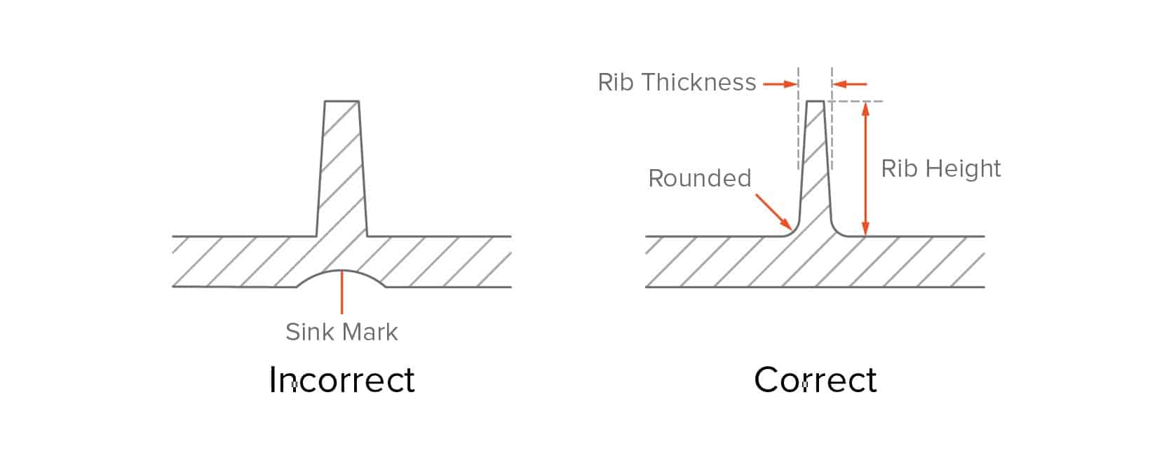
Use the following language consistently in CAD reviews:
| Term | Meaning |
|---|---|
| Nominal parent-wall thickness | |
| Rib or gusset thickness at its root | |
| Cylindrical wall thickness of a cored boss | |
| Rib height, measured from the parent wall to the rib tip | |
| Boss hole or core diameter | |
| Boss outer diameter | |
| Class-A surface | Customer-visible or appearance-controlled surface |
| B-side | Non-visible functional side of a trim, housing, or molded component |
The feature dimensions in this lesson are DFM screening rules, not a substitute for a material supplier’s data, fastener supplier recommendations, or mold-flow results. Glass-filled materials, flame-retardant grades, textured surfaces, part geometry, gate location, and customer appearance requirements can all justify a tighter requirement.
[PDF] Eastman polymers processing and mold design guidelines
Read the rib-and-boss guidance in Eastman’s Polymers Processing and Mold Design Guidelines. It gives a useful set of practical dimensions for feature thickness, height, spacing, radii, and draft, while also explaining why these rules protect both structural performance and molding quality.
On p. 6, in the subsection “Rib and boss design,” read the full rib and boss discussion. Focus on the distinction between a rib’s root thickness, its height, its spacing from neighbouring ribs, and the boss’s cored-hole geometry. Then go to p. 5, in “Stress concentration factors,” and read the explanation of radii and coring. Notice the trade-off: too small a radius creates a crack-initiation site, while too large a radius may create a thick section. Finally, on p. 25, read the opening paragraphs of “Draft angle guidelines,” beginning with the general draft guidance. Use it as a starting point for ribs and bosses; texture, depth, material shrinkage, and toolmaker advice can require more draft.
Ribs: the first choice for stiffness
A rib is a thin, upright reinforcing wall connected to a parent wall. It is normally preferable to making the entire parent wall thicker because it adds section depth only where stiffness is needed. Ribs are particularly effective when they are aligned with the actual bending load path.
For example:
- An ECU base may need ribs running from a vehicle mount into the enclosure floor or side wall.
- A door carrier may need shallow B-side ribs to resist local clip and pull-handle loads while protecting the visible trim surface.
- An HVAC outlet housing may use ribs to keep a bezel flange flat, support a pivot housing, or stabilize a duct wall.
The visible-surface rib rule
For a visible Class-A surface, use:
A practical starting range is:
The lower end reduces sink risk; the upper end may be needed when stiffness, molding robustness, or material flow requires it. Do not begin at for a Class-A-backed rib merely because it is a common generic guideline. Where surface appearance governs, is the appropriate maximum screening limit for this course.
For non-visible regions, a supplier may permit a rib nearer , depending on resin, wall thickness, gate strategy, and acceptable cosmetics. That is a decision to document and validate, not an automatic entitlement.
Suppose the nominal wall is:
For a rib behind a visible surface:
A sensible concept choice is:
That dimension applies at the rib root, where the rib meets the parent wall. If draft is applied correctly, the rib becomes thinner toward its tip.
Rib height, spacing, radius, and draft
A thin rib can only contribute stiffness if it has adequate height. But a very tall, unsupported rib becomes difficult to fill, cool, and eject, and can buckle under loading.
Use these initial screens:
| Rib parameter | Initial DFM target | Why it matters |
|---|---|---|
| Root thickness | to behind visible surfaces | Limits sink and read-through |
| Rib height | in most structural applications | Controls slenderness and thin rib tips |
| Clear rib spacing | At least | Leaves tool steel for cooling and avoids a field of local heavy sections |
| Root radius | to , subject to section review | Reduces stress concentration |
| Draft | Start at per side where practical | Supports ejection and avoids drag |
With , these preliminary values become:
The root radius requires judgment. A zero-radius rib is a stress riser. An oversized radius can add enough material at the root to recreate the sink problem that the thin rib was intended to avoid. Inspect the section, rather than accepting a radius because it looks smooth in shaded CAD view.
Injection Molding Design Tips - 10 DFM Guidelines
Watch the short rib-and-boss overview in Injection Molding Design Tips – 10 DFM Guidelines by RAPID DIRECT. It is useful as a visual reminder that reinforcement, spacing, and local wall thickness must be considered together.
Watch ribs and gussets for the relationship between nominal wall thickness and reinforcement thickness. Then watch boss support for the idea that a boss should be structurally tied into its parent part rather than left as an isolated tower. Treat the numerical values as initial DFM guidance and reconcile them with the more specific material, appearance, and fastener requirements of your component.
Place ribs according to the load path
A rib does not “add stiffness everywhere.” Its orientation determines what deformation it resists.
Consider an ECU housing floor carrying a mounted PCB and connector loads. Ribs that run from mounting bosses toward the enclosure side wall can distribute mounting reaction loads. Randomly oriented ribs might make the floor look reinforced while doing little to control the actual bending mode.
For a door trim carrier, the opposite Class-A surface changes the priority. A deep, thick rib directly behind a show surface creates sink and read-through risk. Better options include:
- moving the load path toward a hidden return flange or perimeter wall;
- using several shallower ribs instead of one large rib;
- placing a rib where it terminates before the most appearance-sensitive surface;
- using local curvature, a bead, or a boxed return for stiffness;
- accepting a supplier-reviewed appearance risk only when the feature cannot be relocated.
A rib should also avoid ending abruptly in the middle of a flexible field. Taper or blend it out gradually, and do not let its termination create a sharp stiffness discontinuity that could telegraph through a visible surface.
Gussets: supporting a local load introduction
A gusset is usually a triangular or tapered reinforcing web that stabilizes a wall, boss, post, flange, or bracket-like feature. While a rib reinforces a longer span, a gusset is often used where a concentrated load enters the part.
Common applications include:
- supporting an ECU mounting boss against shock and fastener clamp load;
- supporting a door-carrier clip tower or screw attachment;
- tying an HVAC outlet pivot housing into the duct body;
- stabilizing a thin flange that receives assembly or service loads.
The important rule is that a gusset is still a secondary wall. At its root, it should normally follow the same thickness discipline as a rib:
where the gusset lies behind a visible surface.
A gusset with a very thick triangular base is not structurally “safer” in a molding sense. It behaves as a thick mass at the intersection, cools slowly, and can create a sink opposite the root. Instead, use a drafted, tapered web with an appropriate root radius and enough length to transfer load into a stiffer region.
A useful gusset design sequence
When designing a gusset, proceed in this order:
- Identify the applied load. Is it a fastener clamp force, a lateral service load, a clip insertion load, vibration, or an impact load?
- Identify the reaction structure. The gusset must connect the loaded feature to a wall, flange, return, or mount that can actually carry the force.
- Set the root thickness. Use the same to starting range for visible-surface-sensitive regions.
- Add draft and a controlled root radius. These are functional DFM features, not cosmetic finishing.
- Inspect the combined cross-section. Confirm that multiple gussets, a boss, and a nearby wall do not combine into one thick thermal node.
- Check tooling direction. A gusset that creates an undercut or has insufficient draft may require a side action or a redesign.
For a boss near a side wall, two or three thin gussets are frequently better than merging the boss into the wall with a large solid bridge.
Screw bosses: cored attachment towers, not solid posts
A boss is a cylindrical or near-cylindrical molded feature used for a screw, threaded insert, pin, locating function, pivot, or standoff. It should be treated as a hollow structural feature: the center bore is not optional empty space; it is part of the strategy that controls cooling, shrinkage, and moldability.
A solid boss may appear strong in CAD, but it creates a thick section at the parent wall and increases the likelihood of sink, voids, and long cooling time. The default should be a cored boss.
Boss geometry begins with the interface
Do not size a boss by choosing a visually convenient outside diameter. Begin with the assembly interface:
- fastener type, nominal size, and thread-forming or machine-thread strategy;
- required thread engagement;
- pilot-hole diameter, if using a thread-forming screw;
- insert supplier’s outer diameter, installation hole, and pull-out or torque-out requirements;
- access for a driver, heat-staking tool, insert-installation head, or assembly fixture;
- local service and replacement requirements;
- expected clamp load and external loads;
- environmental cycling, particularly for polymer-metal assemblies.
Once , the functional bore diameter, is established, the boss outer diameter can be represented as:
where is the molded cylindrical wall thickness. For a cosmetic-sensitive component, start the boss wall near the same range used for ribs:
This is only the first screen. A threaded-insert supplier may require a particular surrounding boss geometry, and that requirement takes precedence once it is approved. If the boss must be heavier for strength, the response should be to improve the load path, use ribs or gussets, and obtain mold-flow and supplier input—not simply to leave a solid tower behind a show surface.
Boss height, radii, and support
The Eastman guidance gives an especially useful limit for a molded screw or insert boss:
where is the effective boss-hole length and is the core or hole diameter. A very long, narrow core pin can deflect under injection pressure and is difficult to cool. It can produce an inaccurate, oval, or poorly controlled bore.
For a bore, the initial limit is:
That does not mean that every tall boss is structurally sufficient. It means a taller bore is a tooling and cooling concern that requires an explicit toolmaker review.
At the boss base, use the larger of:
or
For :
Therefore:
The boss should be separated from a side wall where possible and connected by thin ribs or gussets. This keeps the local mass controlled while producing a much more reliable load path than an unsupported tower.
A practical boss should also include:
- draft on both outer and inner surfaces;
- a lead-in chamfer or rounded entry to guide the screw or insert;
- a controlled top edge rather than a sharp stress-raising rim;
- clearance between adjacent bosses sufficient for cooling-tool steel and assembly access;
- a section review at the boss-to-wall intersection.
Inserts: combining polymer geometry with a metal interface
A threaded insert is used when the joint needs durable, repeatable internal threads beyond what a direct thread-forming screw in plastic can provide. Insert use is common in enclosures that may be serviced repeatedly, see meaningful clamp load, or require a controlled metal-thread interface.
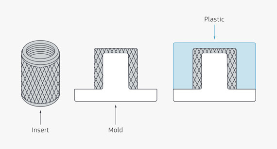
Two broad approaches are relevant:
| Strategy | Description | Main design implications |
|---|---|---|
| Insert molding | The metal insert is loaded into the mold and plastic is molded around it | Requires mold retention, loading strategy, insert positioning, and supplier process control |
| Post-mold insertion | The insert is installed after molding, commonly by heat, ultrasonic energy, or press fit | Requires a supplier-defined installation hole, access, fixture strategy, and validation of installation damage |
For either strategy, the insert supplier’s data sheet controls the final boss design. It should specify the insert type, outside diameter, recommended hole geometry, engagement depth, installation method, allowable torque, pull-out resistance, and recommended polymer families.
Insert-feature DFM rules
Use these rules at concept stage:
- Keep the boss cored. Do not create a solid cylinder around an insert simply to make it feel robust.
- Use the insert supplier’s recommended bore. The installation hole is a functional dimension, not a generic clearance hole.
- Provide adequate polymer around the insert. The boss must resist hoop stress during installation and in service, but should not create a thick root against a visible wall.
- Support the boss with ribs or gussets. The support should carry external loading into the parent structure rather than making the cylindrical wall excessively thick.
- Protect appearance surfaces. Do not place an insert boss directly behind a Class-A surface unless sink/read-through has been assessed and accepted.
- Allow process access. Post-mold inserts require room for an installation head and fixture. Molded-in inserts require a retention method that prevents movement during fill.
- Consider thermal expansion. Metal and polymer expand differently. Temperature cycling can affect clamp load, local stress, sealing, and crack risk.
- Plan validation. Pull-out, torque-out, installation quality, screw cycling, environmental exposure, and housing crack inspection should appear in the component validation plan.
For an ECU housing, metal inserts may be justified at cover fasteners or vehicle mounting interfaces. Their proximity to electrical-isolation boundaries, gasket lands, and thermal paths makes the decision more than a fastening choice. It needs to be traced to the requirement, material selection, validation evidence, and released CAD revision.
For a door carrier, an insert may be appropriate in a repeated-service interface, but it should not be assumed simply because the part is automotive. A clip, direct thread-forming screw, or separate bracket may offer a lower-risk solution depending on load, service frequency, and appearance location.
Worked feature-sizing example
Assume a preliminary molded enclosure has:
A rear-side feature zone must support a fastener boss, while the opposite surface is customer-visible.
Rib selection
Select a rib root thickness:
Round this to a controllable CAD value:
Set a preliminary height limit:
Set clear spacing between parallel ribs:
Use a root radius and draft per side as an initial model. The root thickness remains the governing sink-risk dimension.
Boss selection
Assume a preliminary cored bore is required by the fastening concept. Choose a cosmetic-side cylindrical boss wall:
This corresponds to:
The outside diameter becomes:
If the effective bore length is :
This meets the initial screening limit. The boss is then supported with two -root gussets or ribs, positioned so their roots do not sit directly beneath the appearance-critical surface.
The review conclusion is not “the boss is approved.” It is:
Concept geometry meets initial feature-proportion screens. Confirmation remains open pending fastener/insert supplier geometry, mold-flow review, structural loading, and appearance evaluation.
That distinction is important in an IATF-aligned development record: an early engineering calculation is evidence of a controlled decision, not false certainty.
CAD method and controlled DFM evidence
In Onshape, begin by defining variables in the Part Studio or recording them in a controlled design table:
| Variable | Example value |
|---|---|
T_nominal | |
rib_root | |
rib_height_max | |
rib_spacing_min | |
boss_bore | |
boss_wall | |
boss_outer_diameter | |
boss_base_radius | minimum |
A robust feature workflow is:
- Create the nominal shell first and establish the tooling direction.
- Sketch the rib, gusset, or boss from stable parent references rather than incidental edges.
- Model ribs as thin, drafted webs with a rounded root.
- Model bosses as cored cylinders, then add the functional bore, draft, lead-in, and support ribs or gussets.
- Create section views through every critical intersection: rib-to-wall, gusset-to-boss, boss-to-wall, and insert-to-boss.
- Measure root thicknesses, spacing, bore length, wall thickness, and local accumulations.
- Use draft analysis in the appropriate pull direction.
- Save a named Onshape version before major DFM changes and record the change rationale.
In CATIA V5 or 3DEXPERIENCE CATIA, the equivalent intent is to drive these features through parameters, stable published references, Part Design pads and pockets, Draft, Edge Fillet, and analysis tools. The command names differ from Onshape, but the evidence required for a design review does not.
Create a controlled Feature DFM Register for each project. It can be a spreadsheet or a PLM-linked document while you lack ENOVIA access.
| Field | Example |
|---|---|
| Feature ID | ECU-BOSS-014 |
| Part and revision | ECU base, Rev A concept |
| Feature function | Cover fastener attachment |
| Parent wall | |
| Root-wall ratio | |
| Hole and height ratio | |
| Support strategy | Two gussets to enclosure wall |
| Appearance classification | Hidden B-side; no Class-A surface opposite |
| Insert or fastener status | Direct screw concept; supplier confirmation open |
| DFM evidence | Section, draft image, thickness check |
| Open risks | Fastener torque and mold-flow confirmation |
| Linked CAD version | Onshape version identifier |
| Approval maturity | Concept reviewed / supplier review pending |
This register is especially useful when a supplier later identifies a sink mark, cracked boss, poor insert retention, or core-pin concern. The ECO can then link the issue to the original feature intent, the affected CAD and drawing dimensions, the revised DFM evidence, and the validation record.
A practical review routine
Before sending a part to supplier feasibility review, inspect all secondary features using this sequence:
- Find each rib root. Is it at or below where the opposite surface is visible?
- Check every rib field. Are ribs sufficiently spaced, drafted, radiused, and aligned with a real load path?
- Section each gusset. Does the gusset reinforce the feature without becoming a thick triangular mass?
- Inspect every boss. Is it cored, drafted, radiused, and supported rather than left as an isolated post?
- Review every insert interface. Is the geometry based on approved supplier data, with installation and tool access considered?
- Look at the opposite surface. For each boss, rib, and gusset, identify whether a Class-A surface, sealing land, datum, or critical interface lies on the other side.
- Identify stacked features. A boss plus ribs plus a nearby wall may create a heavy section even when each individual feature appears compliant.
- Record uncertainty. Material grade, gate location, fastener data, cosmetic acceptance, and mold-flow results may remain open at concept stage. State that explicitly.
Key takeaways
Ribs, gussets, bosses, and inserts allow a plastic part to meet stiffness and attachment requirements without thickening the primary shell.
- For features behind visible surfaces, use the conservative screening rule:
- Start visible-surface ribs and gussets around to , add draft and a controlled root radius, and inspect the combined wall thickness at their bases.
- Use ribs and gussets to create a genuine load path; geometry that merely adds mass does not necessarily add useful stiffness.
- Model screw bosses as cored features. Start from the fastener or insert interface, then size the boss wall, height, support, and access around it.
- Screen molded boss-hole proportions using:
unless the toolmaker and supplier approve another design.
- Treat inserts as a polymer-metal system requiring supplier geometry, installation planning, local support, thermal-expansion consideration, and validation.
- Capture feature dimensions, sections, draft evidence, assumptions, risks, and CAD revision in a controlled DFM register.
Next, you will determine suitable minimum draft angles from pull direction, draw depth, texture, and polymer shrinkage—turning these feature concepts into geometry that can reliably release from a mold.
Can't find a good explanation? Sign up and we'll make it for you
Sign up