
Hello. In the previous lesson, you established tooling direction and draft as controlled DFM decisions. You also saw why nominal wall thickness, rib proportions, and gradual transitions must be decided early. Those choices now become diagnostic clues: when a molded part is distorted, incomplete, visibly marked, or dimensionally unstable, its geometry and flow path often explain why.
This lesson develops a practical method for diagnosing six common injection-molding problems: sink marks, weld lines, short shots, air traps, shrinkage, and warpage. The goal is not to memorize a list of settings to change. It is to build a defensible hypothesis from the defect’s location, the part geometry, the gate strategy, and the trial conditions—then test one variable at a time.
Read the molded part as evidence
A molded part records its own manufacturing history. The gate establishes where melt enters; geometry controls resistance to flow and local cooling; packing determines whether cooling shrinkage is compensated; cooling and material orientation influence final shape. A visible defect is therefore a symptom at a particular place and time in the molding cycle.
A useful first distinction is between the three stages where the issue becomes visible:
| Stage | Main question | Typical defects |
|---|---|---|
| Filling | Can molten polymer reach every cavity region while air escapes? | Short shots, air traps, some weld lines |
| Packing and solidification | Can additional melt compensate for shrinkage before the gate freezes? | Sink marks, internal voids, local shrinkage |
| Cooling and post-ejection relaxation | Does the part shrink uniformly in all directions? | Dimensional shrinkage, warpage |
The same feature can contribute to several defects. For example, a thick screw-boss root behind a cosmetic wall can create a sink mark because it cools late. It can also produce an internal void if the skin remains visually intact while the interior continues shrinking. If several heavy features are concentrated on only one side of a housing, their unequal cooling can contribute to global warpage.
Start every diagnosis with four questions:
- Where is the defect? Record the exact location relative to the gate, cosmetic surfaces, ribs, openings, bosses, and parting line.
- Is its location repeatable? A repeatable defect in one region points more strongly to geometry, gate, venting, or local cooling than to random handling damage.
- What does the expected flow pattern look like? Sketch the advancing melt front from each gate, including where fronts divide around holes or reconnect.
- What changed? On a previously stable tool, first inspect material lot, drying records, regrind ratio, machine maintenance, temperatures, and process-window drift before assuming the CAD is at fault.
This distinction matters in a company setting. A geometry-driven issue may require a supplier DFM action and an ECO. A controlled process adjustment may require a documented trial and an updated process window, but not necessarily revised product CAD.
A compact defect atlas
The following guide is deliberately phrased as likely causes, not automatic conclusions. Defects are often multi-factor problems.
| Defect | What you observe | Geometry and gate clues | Process clues | First diagnostic action |
|---|---|---|---|---|
| Sink mark | Local surface depression | Thick wall, boss root, rib root, gusset, or mass concentration behind the affected surface; feature far from gate | Low pack pressure, insufficient hold time, early gate freeze | Check local section thickness and perform a gate-seal/part-weight study |
| Weld line | Line where two flows meet; may be cosmetic or structurally weak | Flow divides around an opening, central boss, or insert; multiple gates; weld lies on a load path or Class-A surface | Melt fronts too cool or low-pressure when they meet | Draw the fill pattern and assess whether gate relocation can move the line |
| Short shot | Cavity does not fill completely | Thin wall, long flow path, abrupt restriction, restrictive gate, remote end of a large part | Low fill speed, low melt temperature, inadequate pressure or shot size, poor venting | Run a controlled short-shot study and identify the actual last-fill region |
| Air trap | Burn mark, compression mark, trapped-gas blemish, or local failure to fill | Blind pocket, converging flow fronts, end-of-fill region, rib pocket, boss pocket | Excessive fill speed can compress air; vents blocked, shallow, or misplaced | Locate last fill; inspect vent location and vent condition before increasing pressure |
| Excess shrinkage | Overall undersize, variation from nominal dimensions, local contraction | Thick-to-thin transitions, long unsupported dimensions, gate far from critical dimensions | Insufficient or inconsistent packing, early gate freeze, material or temperature variation | Compare measured dimensions by region and review packing, gate seal, resin data |
| Warpage | Bowing, twisting, cupping, or loss of flatness | Uneven walls, asymmetric rib pattern, heavy features on one side, unbalanced form | Unequal cooling, residual orientation stress, unequal packing, fiber orientation effects | Measure shape at ejection and after conditioning; compare cavity and core cooling conditions |
A sink mark is not simply “a low-pressure defect.” It begins with a local thermal problem: a thick section remains molten while the thinner skin near the visible surface has already solidified. As the thick region contracts, it pulls the surface inward. More packing can help only while the gate remains open and transmitting pressure.
The rib guideline from the prior lesson is directly relevant here. If a visible wall has nominal thickness , starting a rib near or below reduces the heavy mass at the rib root. But the root region still deserves a section check: a thin rib attached to an already-thick wall, or several ribs converging at one point, can still create a local hot spot.
Injection Molding Guide: Process, Design Tips & Materials - Protolabs
Read Protolabs’ compact defect table to connect visible defect signatures to the design choices that commonly create them. It reinforces the geometry-first checks you should make before proposing a process change.
In the section “Common Injection Molding Defects and Design Fixes,” read the defect table. Then continue to the design guidance immediately below it, especially the wall-thickness and gate-planning guidance. Focus on the distinction between removing unnecessary mass and merely trying to compensate for poor geometry with process settings.
Sink and shrinkage: separate the symptom from the mechanism
All thermoplastics shrink as they cool. Shrinkage itself is normal and is accommodated in tool dimensions, material data, and tolerance planning. It becomes a quality problem when shrinkage is excessive, inconsistent, directional, or locally concentrated.
A practical hierarchy for a sink-mark investigation is:
- Inspect the section. Use CAD sections through the defect and identify total local mass, not just one dimension. Look behind visible Class-A surfaces for boss bases, intersecting ribs, doghouses, or solid corner blocks.
- Check whether packing can reach the region. A gate that freezes before the thick section is adequately packed disconnects the cavity from the pressure source.
- Run a gate-seal study. Mold parts at increasing hold times and compare their mass. Once part mass stops increasing, the gate has frozen. Additional hold time cannot add material.
- Only then decide the corrective path. If more packing while the gate is open resolves the issue, a process or gate-sizing action may be sufficient. If sink persists after gate freeze, revise the geometry, move the gate, or both.
This prevents a common failure mode: increasing pack pressure until sink is less visible, while creating flash, residual stress, ejector marks, or warpage elsewhere.
For a door-trim carrier, imagine four stiffening ribs merging into a solid doghouse directly beneath a Class-A region. Even if each individual rib nominally meets a rib-thickness guideline, the combined junction may be too massive. A better B-side concept may split the load path into separated ribs, core out the doghouse, or move the attachment feature away from the cosmetic zone.
For an ECU housing, a thick sealing flange near a corner may be functionally necessary. The design task is not to make every zone identical, but to transition thickness gradually, provide a credible packing route, and flag the region for mold-flow and trial-part scrutiny.
Flow fronts explain weld lines, short shots, and air traps
During filling, molten polymer behaves like an advancing front. Its path is shaped by wall thickness, gate location, obstacles, changes in direction, and cooling against tool steel.
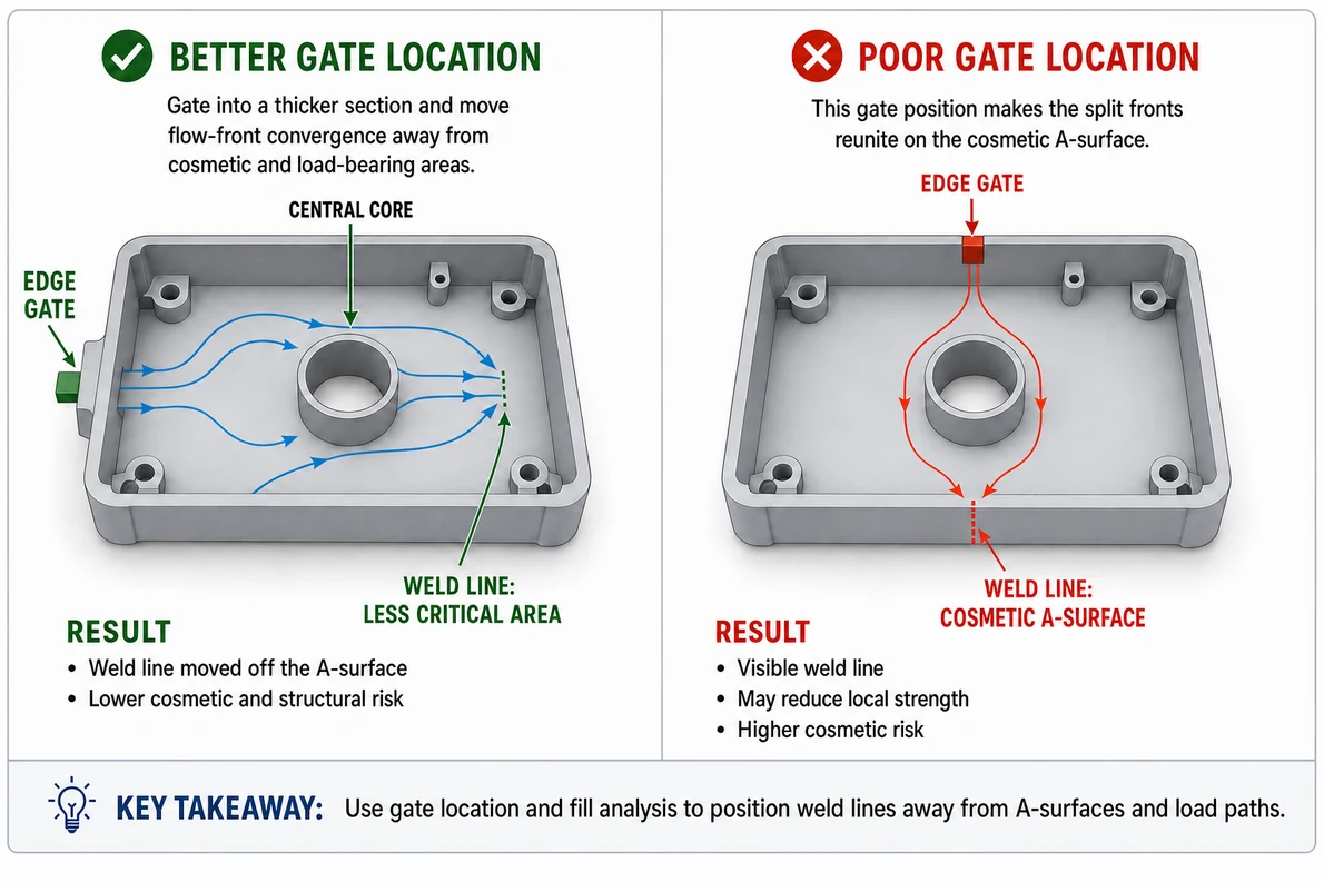
A weld line forms where two melt fronts meet. This often happens where flow divides around a hole, central boss, insert, or large opening and later reunites. The line may be mainly cosmetic, but it can also be a structural weakness if the fronts meet cold and fail to fully fuse.
A weld line is not always avoidable. The higher-value design decision is to control where it occurs:
- Do not allow it to fall across a visible Class-A surface if another gate strategy can move it.
- Do not place it across a pull-handle load path, screw-boss load path, or sealing land.
- Consider a gate location that lets the weld line form in a low-stress, hidden region.
- Use temperature, fill speed, and pressure tuning to improve fusion only after confirming that the basic gate strategy is credible.
A short shot occurs when the melt front freezes or is blocked before filling the cavity. The incomplete area is often at the end of a long, thin flow path, but do not assume that a short shot proves insufficient pressure. Trapped air can create back-pressure that produces the same incomplete-fill appearance.
An air trap is gas that cannot escape ahead of advancing melt. It often occurs at the last-fill region, in a blind end, or where flow paths converge. Compressed air may leave a burn mark, sometimes called a diesel-effect burn, because rapid compression heats the gas intensely. If an air trap is the root cause, raising injection pressure may intensify the burn or force flash elsewhere without completing the fill reliably.
Plastic Injection Molding Troubleshooting Guide: Diagnosing and Fixing Common Defects
Use this troubleshooting guide as a trial-planning reference. Its most valuable message is methodological: distinguish geometry, tool, material, and process hypotheses, then make controlled changes rather than adjusting every machine setting at once.
Read the subsections “Short Shots: Why the Cavity Doesn't Fill Completely” and “Sink Marks: Root Causes and Wall Thickness Effects.” Follow the short-shot diagnosis, then read the sink-mark hierarchy. Note the use of vent inspection and gate-freeze evidence to distinguish causes. Next, in “Burn Marks and the Diesel Effect” and “Weld Lines and Flow Lines: Cosmetic and Structural Risks,” study last-fill venting and weld-line formation. Finally, review the “Process Parameter Cross-Reference for Common Defects” table and the troubleshooting workflow. Treat the parameter matrix as a guide to trade-offs, not a set of independent fixes.
Diagnose with a controlled trial, not with parameter guessing
A repeatable engineering diagnosis requires a record that someone else can review and reproduce. During a supplier trial, create a defect location map on a part image or drawing view. Mark:
- gate and runner locations;
- nominal wall thickness zones;
- rib, boss, and gusset roots;
- last-fill estimate;
- visible surfaces and load paths;
- defect type, size, direction, and frequency;
- cavity number, material lot, drying condition, tool temperature, melt temperature, fill speed, pack pressure, hold time, cooling time, and machine identity.
Then use this sequence:
- Classify precisely. “Cosmetic issue near the corner” is not usable. Record “sink mark, maximum depth, on exterior wall behind boss B03, from the gate.”
- Form competing hypotheses. For that example: excessive boss-root mass; insufficient pack; gate freeze before pack reaches B03; or a combination.
- Choose the lowest-risk discriminating test. A controlled hold-time and part-weight study tests gate freeze. A section review tests geometry. A fill study identifies last-fill and likely vent locations.
- Change one variable category at a time. Keep the other relevant parameters controlled. Otherwise, you cannot tell whether speed, temperature, pressure, or a new vent actually improved the part.
- Verify repeatability. A single visually acceptable part is not evidence of a stable process. Confirm over a small defined run and inspect the critical dimensions and appearance zones.
- Decide ownership and traceability. Record whether the result needs a process-window update, tool modification, CAD revision, drawing update, or formal ECO.
For the simulated EDV projects, this is where engineering judgment becomes PLM evidence. A supplier may report “sink improved with packing.” The controlled project record should still state whether the cosmetic acceptance criterion was met, whether the process is robust, whether a B-side CAD change is needed, which CAD revision was evaluated, and who approved closure.
Warpage is unequal shrinkage made visible
Warpage is not simply “a part that shrank.” If every location and direction in a part contracted uniformly, the part would become smaller but retain its shape. Warpage occurs when contraction is unequal across the part.
Unequal shrinkage can arise from:
- uneven wall thickness;
- asymmetric ribs, bosses, flanges, or gussets;
- unequal cooling between cavity and core sides;
- cooling channels that are too distant from local hot spots;
- gate location and packing gradients;
- flow-induced molecular orientation;
- fiber orientation in glass-filled materials;
- ejection before the part is dimensionally stable.
For a glass-filled ECU polymer such as PA66-GF30, warpage assessment deserves special caution. Fibers tend to align with flow, and shrinkage may differ along and across the flow direction. A gate change can therefore change fiber orientation and distortion direction, even if the nominal wall thickness remains unchanged.
For a PP-based door carrier, broad surfaces, uneven B-side reinforcements, and long flow lengths make the geometry and cooling balance central concerns. Adding material only to “make it stiffer” may worsen the thermal imbalance that drives distortion.
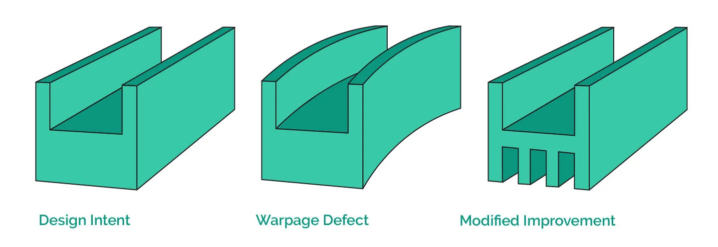
The U-shaped example is important because it challenges a simplistic rule: adding holes or ribs does not automatically reduce warpage. A geometry change must allow more balanced contraction or create a more symmetric structure. The modified design in the image uses internal structural features to change how the section resists and accommodates differential contraction.
Kruse Training Webinar: Understanding Shrinkage and Warpage
Watch selected segments of Kruse Training’s “Understanding Shrinkage and Warpage.” The webinar gives a rigorous physical explanation of why uniform shrinkage changes size but unequal shrinkage bends a part, then applies that idea to U-shaped molded geometries.
In the segment beginning at 9:16, watch the shrinkage principle. Focus on the distinction between uniform dimensional reduction and asymmetric volumetric shrinkage that produces warpage. Then, within the later U-shaped-part case study, begin at the discussion of the cutout iteration and watch the geometry comparison. Observe why cutouts reaching the base and the more balanced I-beam-like form reduce distortion much more effectively than a superficial geometric change.
A valuable trial technique is to inspect warpage at more than one time:
- measure the part shortly after ejection;
- measure after a controlled room-temperature conditioning period;
- compare the direction and magnitude of shape change.
Immediate and persistent distortion can indicate molded-in orientation stresses or strongly asymmetric shrinkage. Shape change that continues during conditioning can indicate stress relaxation or thermal imbalance. This does not replace mold-flow simulation or thermal analysis, but it gives a disciplined basis for the next hypothesis.
Design, gate, and process: choose the right level of correction
When proposing corrective action, use the least disruptive action that addresses the confirmed mechanism—but do not use process tuning to hide a flawed design.
| Confirmed mechanism | Preferred response |
|---|---|
| Local heavy mass causes sink after the gate has frozen | Core out the mass, separate intersecting ribs, revise the boss or gusset architecture, or alter gate location/size |
| Weld line lies on a visible or load-bearing area | Relocate or redesign the gate strategy to move the line; then confirm fusion quality with process settings |
| Short shot occurs at a thin, remote end but venting is adequate | Reassess flow length, wall thickness, gate size, runner strategy, melt condition, and machine capacity |
| Burn appears at the confirmed last-fill point | Provide appropriate venting at that specific location; verify that fill speed is not unnecessarily severe |
| Warpage follows asymmetric geometry or cooling | Balance wall sections, feature layout, gate strategy, and core/cavity cooling; account for fiber orientation where applicable |
| Dimension varies part-to-part with no geometry change | Investigate pack/hold consistency, material condition, gate seal, cooling, and machine repeatability before altering CAD |
For design review, avoid writing “increase pressure” as the final corrective action. A stronger statement is:
Sink mark at the Class-A region behind boss B03 is associated with a locally heavy boss-wall junction and insufficient packing after early gate freeze. A hold-time study will establish gate-seal time. If sink remains after gate seal, redesign boss B03 with a cored base and separated support ribs; evaluate the revised geometry with mold-flow analysis and supplier DFM review.
That statement identifies the symptom, mechanism, evidence plan, fallback geometry action, and release implication.
Key takeaways
A successful defect diagnosis connects the observed part to the physical stage in which the problem arose.
- Sink marks are local surface depressions caused by shrinkage in heavy sections after the outer skin has set. Check geometry and gate-seal behavior before escalating pressure.
- Weld lines occur where melt fronts meet. Their location is often more important than their mere existence: move them away from cosmetic and load-bearing zones through gate strategy.
- Short shots are incomplete fills caused by restricted flow, cooling, inadequate filling capability, or trapped air. Identify the real last-fill location.
- Air traps are venting problems during filling. They commonly create burns or incomplete fill at the last-fill region; more pressure is not a reliable first response.
- Shrinkage is normal polymer contraction; it becomes a defect when excessive, inconsistent, or dimensional-critical.
- Warpage is the result of unequal shrinkage. Geometry, gate placement, cooling balance, process conditions, and fiber orientation can all contribute.
- Use location maps, controlled trials, single-variable changes, repeatability checks, and a documented ownership decision. This converts trial-and-error into traceable engineering evidence.
In the next module, you will shift from individual DFM decisions to CAD and product-structure control: organizing a multi-part plastic assembly in Onshape and mapping that structure to CATIA and ENOVIA concepts.
Can't find a good explanation? Sign up and we'll make it for you
Sign up