
Welcome back. In the previous lesson, you made class and interface boundaries explicit through contracts: inputs, outputs, failures, side effects, and invariants. A UML class diagram is the compact visual form of many of those decisions. It lets an interviewer quickly see which objects exist, what each object owns, and how collaboration is structured.
This lesson focuses on drawing a small, interview-ready UML class diagram. You will learn to choose an appropriate level of detail, represent classes and interfaces, model relationships and multiplicities, and build a diagram from a narrow parking-lot use case. The goal is not decorative UML; it is a diagram that makes a defensible object-oriented design easy to discuss.
A class diagram is a static design argument
A UML class diagram describes the static structure of a design:
- the important classes or interfaces;
- key state and public behavior;
- structural relationships among objects;
- cardinality and ownership rules.
It does not show the chronological execution of a request. You will use a sequence diagram for that in the next lesson. For now, think of the class diagram as answering:
“What are the core objects, and what stable relationships must exist among them?”
In an LLD interview, a good class diagram should emerge from the requirements and the contracts you already identified. It should make clear:
- Which concepts have their own responsibilities.
- Which behaviors are replaceable behind an interface.
- Which objects have a lifetime/ownership relationship.
- How many instances may participate in each relationship.
Do not treat it as a database ER diagram. A database schema emphasizes tables, foreign keys, and persistence. A class diagram emphasizes behavior, encapsulation, and object collaboration.
Before continuing, watch the short foundation below. It covers the notation you will use without going into unnecessary tool-specific detail.
Watch “UML class diagrams” from Lucid Software. It gives a visual introduction to class boxes, visibility, relationships, and multiplicity—the notation needed to read and create an interview-scale diagram.
Watch class anatomy to see how class names, attributes, operations, and visibility are written. Then watch relationships, focusing on the lifetime distinction between aggregation and composition and on where multiplicity labels are placed.
The class box: include meaningful state and behavior
A UML class is normally a rectangle with up to three compartments:
- Class name
- Attributes, or meaningful stored state
- Operations, or public behavior
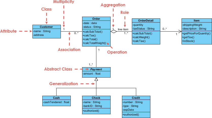
A simplified UML class might look like this:
ParkingTicket
----------------------------
- id: TicketId
- enteredAt: datetime
- exitedAt: datetime [0..1]
- finalFee: Money [0..1]
----------------------------
+ close(exitAt: datetime, fee: Money): void
The visibility markers are conventional:
| Marker | Meaning | Typical use in an LLD diagram |
|---|---|---|
+ | public | Operations that form the class contract |
- | private | Internal state protected by the object |
# | protected | Members intended for subclasses |
~ | package | Rarely useful in a Python interview design |
For Python, - should not be read as a claim of runtime enforcement: Python uses conventions such as _field rather than hard private fields. In UML, the marker communicates the design intent: external code should not mutate this state directly.
A useful interview convention is:
- Show only the key private attributes that establish the object’s responsibility or invariants.
- Show only the public operations that matter to the main use case.
- Do not clutter the diagram with constructors, getters, setters,
__repr__, or framework methods.
For example, ParkingTicket.close() belongs in the diagram because it protects the ticket lifecycle. A separate public setFinalFee() would be suspicious: it allows callers to break the invariant that a ticket’s final fee is established when it closes.
The operation signatures should reflect the contracts from the previous lesson:
+ quote(duration: Duration, vehicleType: VehicleType): Money
This tells the reader that pricing is a behavior with typed inputs and a monetary result. The diagram does not need to spell out every precondition, but you should be ready to state the important ones verbally:
“
quoteaccepts a non-negative duration and returns a non-negativeMoneyvalue without changing ticket state.”
Three useful levels of class diagrams
Not every diagram needs the same amount of implementation detail.
| Perspective | What it shows | Interview use |
|---|---|---|
| Conceptual | Domain concepts and relationships | Early exploration of the problem space |
| Specification | Interfaces, public operations, important contracts | Usually the best target for LLD interviews |
| Implementation | Language-specific fields, types, private members, concrete classes | Use selectively when you are about to code |
For a typical LLD answer, begin near the conceptual/specification boundary. Add concrete field types and private state only when they clarify an invariant or important behavior.
Read Visual Paradigm’s “What is Class Diagram?” as a concise notation reference. It is most useful here for checking relationship symbols, visibility markers, and the level of abstraction appropriate for a diagram.
In the “Class Relationships” section, read the relationship overview and compare each relationship to the lifetime rules discussed below. Then, in “Visibility of Class attributes and Operations,” review the visibility conventions. Finally, read the “Perspectives of Class Diagram in Software Development Lifecycle” discussion of the three perspectives; focus on why a design can be useful before it becomes implementation-level code.
Relationships: model meaning, not line decoration
Most diagram mistakes are relationship mistakes. The fact that two classes are connected should convey a specific claim about the design.
Association: a stable structural connection
An association is the ordinary relationship between objects that know about or work with each other. It is drawn with a solid line.
Examples:
- A
ParkingTicketrecords theVehiclethat entered. - A
ParkingLotissues manyParkingTicketinstances. - A
ParkingServiceretains a reference to a configuredPricingPolicy.
Use association when the connection is meaningful but neither object’s lifetime is determined by the other.
Composition: ownership with shared lifetime
Composition is a stronger relationship. It means the whole owns its parts, including their lifetime. It is drawn with a filled diamond at the whole’s end.
For example, in a parking-lot domain, a ParkingLot can reasonably be modeled as composed of ParkingSpot objects:
- a spot is created as part of a particular lot’s layout;
- it does not migrate independently to another lot;
- deleting the lot removes its spots from this model.
This is not merely “has a.” Almost every backend object “has a” dependency, but that does not make it composition.
Aggregation: a weak whole-part relationship
Aggregation uses a hollow diamond. It suggests a whole-part relationship where the part can outlive the whole or belong independently.
In practice, aggregation is often ambiguous. For an interview answer, prefer a plain association unless the whole-part meaning is genuinely useful and you can explain why the part survives independently.
Generalization: a genuine “is a” relationship
Generalization is UML’s inheritance relationship, shown by a solid line with a hollow triangle pointing to the parent.
Use it only when the child can substitute for the parent without changing the expected contract. For example, HourlyPricing can implement a PricingPolicy contract, but Car should not automatically inherit from ParkingSpot merely because both occur in the same parking workflow.
For an interface, UML commonly uses a dashed line with a hollow triangle. This says a concrete class realizes the interface’s behavior.
Dependency: temporary use, not a stored relationship
A dependency is a weaker “uses” relationship, usually drawn as a dashed arrow. It is appropriate when one class only needs another temporarily:
- as a method argument;
- as a local variable;
- through a one-off call.
For example, if ParkingService receives a NotificationSender only as a parameter to send_receipt(), it depends on that interface but does not necessarily own or retain it.
A practical distinction:
| Design fact | UML relationship |
|---|---|
| The object stores or permanently knows another object | Association |
| The object creates, owns, and destroys the part | Composition |
| The object temporarily calls or receives another object | Dependency |
| A concrete type fulfills an abstraction’s contract | Generalization or interface realization |

In the e-commerce diagram, notice the filled diamond near Order: it communicates that an OrderLine belongs to the lifecycle of a specific Order. The plain connection from OrderLine to Product has different meaning. Products exist independently of any particular order line, so composition would be incorrect.
Multiplicity: make cardinality rules visible
Multiplicity labels explain how many instances at one endpoint may be related to an instance at the opposite endpoint.
Common multiplicities are:
| Notation | Meaning |
|---|---|
1 | Exactly one |
0..1 | Zero or one |
0..* | Zero or many |
1..* | One or many |
m..n | A bounded range |
Read multiplicity from the opposite side of the relationship.
If a diagram states:
ParkingLot 1 -------- 1..* ParkingSpot
then:
- each
ParkingLothas one or moreParkingSpotobjects; - each
ParkingSpotbelongs to exactly oneParkingLot.
Similarly:
Vehicle 1 -------- 0..* ParkingTicket
means:
- each ticket records exactly one vehicle;
- a vehicle may have zero or many tickets over time.
Multiplicity is a design decision, not a visual afterthought. It often exposes missing requirements:
- Can a member hold more than one active reservation?
- Can an order exist with zero order lines?
- Can a parking spot be unassigned to a lot?
- Is a payment optional before an order is confirmed?
When requirements are unclear, state the assumption explicitly instead of inventing precision:
“I will assume that a ticket is created for exactly one vehicle and exactly one spot. A vehicle may have many historical tickets.”
Build a diagram from one use case
A reliable way to draw a class diagram under interview time pressure is to design around a narrow principal flow.
Consider this parking-lot scope:
A driver parks a vehicle, receives a ticket, and later exits. The system calculates a fee using a replaceable pricing rule.
The scope deliberately excludes payment processing, floor navigation, gates, database repositories, authentication, and notifications. Those may matter later, but including them now would hide the central design.
1. Extract candidate concepts
Start with nouns and responsibility-bearing concepts:
ParkingLotParkingSpotVehicleParkingTicketParkingServicePricingPolicyHourlyPricing
Then filter them.
Money, TicketId, VehicleType, datetime, and Duration are useful types, but they do not all need their own boxes in a small diagram. Money may be a value object in code; VehicleType may be an enum. Keep the diagram focused on the objects whose relationships and behavior you need to discuss.
2. Place state where its invariants belong
The ticket owns the facts about one visit: entry time, optional exit time, and optional final fee. Its close() operation protects the invariant that a closed ticket has both an exit time and a non-negative fee.
The parking spot knows whether it is compatible with a vehicle. The parking lot owns its spots. The service coordinates a use case but should not absorb ticket state or pricing formulas.
3. Make replaceable behavior visible
The pricing rule varies independently of ticket lifecycle and parking-spot allocation. Represent it behind an interface, just as you did with contracts in the previous lesson.
In Python, the interface could correspond to either a Protocol or an ABC, depending on whether shared implementation is needed. UML need only show the abstraction and its implementing class.
4. Draw the core design
This diagram makes several deliberate claims:
- A
ParkingLotcomposes one or moreParkingSpotobjects. - A lot issues zero or more tickets over its lifetime, but a ticket belongs to one lot.
- Each ticket records one vehicle and one allocated spot; vehicles and spots can appear on many historical tickets.
ParkingServicecoordinates entry and exit operations.ParkingServiceworks against thePricingPolicycontract, rather than hard-codingHourlyPricing.HourlyPricingis one implementation of the pricing abstraction, not the only possible future rule.
Notice what is absent:
- No repository or database class, because persistence is not needed to explain this domain model.
- No
Paymentclass, because payment was not part of the scoped use case. - No
findAvailableSpot()implementation details, sorting rules, or database queries. - No large inheritance tree for vehicle types.
That restraint is a strength. A class diagram is useful when every box and relationship answers a design question.
A six-minute interview drawing routine
When asked to produce an LLD class diagram, use this sequence:
-
State the narrow scope.
Name the principal use case you are modeling first. -
List the responsibility-bearing classes.
Begin with about five to eight classes or interfaces, not twenty. -
Add only key fields and public operations.
Use types for important concepts, especially IDs, money, time, status, and externally visible results. -
Draw ordinary associations before diamonds.
Use composition only when lifetime ownership is clear. Avoid hollow-diamond aggregation unless it adds a meaningful distinction. -
Add multiplicities for business rules.
Put them on every relationship that matters to correctness. -
Model variation behind an interface.
If behavior may vary independently, such as pricing, allocation, or notification delivery, show the abstraction and at least one implementation. -
Validate the diagram against one use case.
Mentally trace: Which object receives the request? Which object changes state? Which collaborator performs the variable behavior? -
Explain one or two important choices.
For this design: “ParkingTicketowns lifecycle state, whilePricingPolicyowns the fee rule. This prevents the ticket from becoming dependent on every pricing variation.”
A strong diagram is not one that uses every UML symbol. It is one whose relationships, multiplicities, and interfaces can be defended from the requirements.
Key takeaways
A UML class diagram turns an LLD design into a concise structural explanation:
- Use a class box to show the class name, only meaningful state, and important public operations.
- Treat visibility as an encapsulation signal: private state, public contract.
- Use an association for stable collaboration, composition for shared lifetime ownership, and dependency for temporary use.
- Use inheritance or interface realization only for true substitutability and explicit contracts.
- Add multiplicities to communicate business constraints such as optionality, uniqueness, and one-to-many ownership.
- Keep the diagram scoped to a principal use case; omit infrastructure and speculative classes until they are needed.
- In an interview, narrate the design choices behind the diagram, especially ownership, invariants, and replaceable behavior.
Next, you will complement this static view with a UML sequence diagram. You will trace an entry or exit request across the objects in this parking-lot design and make the runtime collaboration explicit.
Can't find a good explanation? Sign up and we'll make it for you
Sign up