
Hello again. In the previous lesson, you established that a merge or split is not a cosmetic adjustment: it changes the grouping of immutable supervoxels and creates new current root IDs. This lesson supplies the missing safeguard: do not edit until the proposed change survives both local image inspection and global 3D inspection.
The central discipline is to treat the EM imagery and the 3D reconstruction as complementary evidence. The 2D EM sections show the underlying biological structures and membranes; the 3D model reveals the reconstruction’s larger-scale topology and morphology. Neither view alone is sufficient.
By the end of this lesson, you should be able to run a repeatable pre-edit verification pass for either a proposed merge or split, use adjacent sections to test continuity, and use 3D plus Find Path to check the larger consequences of the proposed decision.
The evidence hierarchy: EM first, 3D second, tools in support
A segmentation overlay is a model’s interpretation of the EM volume. It is useful for locating proposed errors, but it is not evidence that the segmentation is correct. The biological evidence is in the grayscale imagery: visible membranes, intracellular texture, vesicles, mitochondria, and the way a process changes from section to section.
Use the views in this order:
- 2D EM evidence: Is there a membrane-consistent continuation or separation through consecutive sections?
- 3D morphology: Does the proposed correction produce a coherent whole-cell shape rather than an implausible attachment, gap, or detour?
- Support tools: Does a segmentation path reveal where the current reconstruction connects the two locations?
This resembles debugging a visual system: the 3D mesh is a rendered aggregate view, while the EM slices are the lower-level source data. A clean-looking 3D connection can still be wrong if the model jumped from one nearby neurite to another at an ambiguous section. Conversely, an ugly or apparently discontinuous mesh can result from a correct neurite passing through difficult imagery.
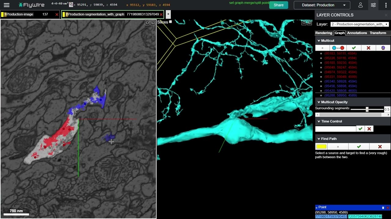
Before beginning a proofread, make sure you can see:
- the EM image layer, without an overlay so opaque that it hides membranes;
- the segmentation overlay, so you can determine which pixels belong to each proposed object;
- the 3D reconstruction, with the relevant root(s) visible and other clutter reduced where possible;
- the current coordinate or crosshair, so that you can return to the exact site.
Read the interface orientation portion of FlyWire 101. It establishes the relationship between FlyWire’s selectable layers, 2D imagery, and 3D segmentation view—the workspace you will use for every verification pass.
In the section beginning “We’ll start by highlighting a few areas of the interface,” read the interface context. Focus on how Layer 2 and its Layer Controls relate to the 3D segmentation, and on selecting or removing a displayed neuron. Exact button layout can evolve, so prioritize the view-management concepts rather than memorizing every control.
A repeatable adjacent-section inspection pass
At the proposed edit site, begin on the section where the candidate connection, break, or erroneous bridge looks most suspicious. Then inspect a short run of slices on both sides of that location. There is no universal number of slices that proves a case: continue until the path is clearly resolved, enters an image defect, or remains genuinely ambiguous.
While scrolling, do not merely ask, “Do the colored regions touch?” Ask whether you can follow the same physical process.
A plausible continuation normally has several features that persist coherently from one section to the next:
| Evidence | What to look for across adjacent sections |
|---|---|
| Membrane continuity | The enclosing boundary shifts gradually and does not reveal a separating membrane at the supposed connection. |
| Interior continuity | Cytoplasm and recognizable internal texture belong to one enclosed profile rather than switching to a neighbor. |
| Position and direction | The profile moves in a geometrically plausible direction as the slice plane advances. |
| Caliber and shape | Diameter may change, especially at branches, but abrupt unexplained changes are a warning sign. |
| Branch logic | A process may divide into branches, but a neighboring process should not silently replace it. |
| Segmentation agreement | Overlay membership follows the visually supported process; it should not leap across a visible gap or membrane. |
A single feature rarely settles a difficult case. Thin neurites may have little visible internal structure, oblique membranes can be faint, and nearby processes can look similar. Seek converging evidence across multiple sections.
The continuity question for a proposed merge
A proposed merge claims that two currently disconnected segmented objects are actually one biological neurite. Start at the endpoint of the known, trusted branch and trace toward the candidate segment one section at a time.
You are looking for a sequence in which the branch:
- approaches the apparent endpoint;
- remains enclosed by a continuous membrane;
- passes through the boundary region without being interrupted by another neurite’s membrane;
- emerges as the nearby candidate segment with compatible direction and caliber.
The candidate is not validated merely because the two endpoints are close in 3D. In dense neuropil, two different neurites can cross, touch visually in projection, or travel side by side for many sections.
A useful verbal test is:
“I can trace one enclosed biological process from the trusted branch into the candidate fragment without crossing a membrane boundary.”
If you cannot say that honestly, do not merge yet.
The separation question for a proposed split
A proposed split claims that a current root contains material belonging to different biological objects. Begin at the apparent attachment, then scroll above and below it.
You are looking for evidence that the segmentation has crossed a boundary it should respect:
- a clear membrane separates the two profiles at the location where the overlay treats them as connected;
- the selected supervoxel or segment appears to span a visible gap;
- one branch’s trajectory continues naturally while the attached branch follows a different cell’s path;
- adjacent sections show that the “bridge” is a jump, a crossing, or an attachment at a synaptic or imaging-ambiguous region rather than cytoplasmic continuity.
The FlyWire 101 guide makes an especially important pre-cut warning: inspect the EM volume to confirm that selected supervoxels do not span the candidate merge gap. A split point placed on an incorrectly interpreted region can detach much more than the small area visible in the current slice.
Read the verification-relevant parts of the merging and splitting guide, then the Find Path description. The operational details are useful, but pay particular attention to the guide’s insistence on checking the EM across the gap before committing a cut.
In “Merging and Splitting,” read from the pre-edit guidance. Follow the merge and split descriptions, but treat them as procedures to use only after evidence is established. Then, in “Find Path,” read the path-tool explanation. Notice its explicit limitation: the path is approximate and represents the current segmentation’s connectivity, not proof that the biological connection is real.
When adjacent sections are unreliable
Sometimes the problem is not the neuron reconstruction alone. EM volumes can contain shifted sections, poor contrast, damaged regions, or missing imagery. These defects are precisely where automated segmentation may make false splits or false merges.
A sudden apparent displacement in every nearby object is evidence for a section misalignment, not for all those neurites abruptly changing direction. In that situation, use a distinctive nearby object as a landmark. Locate the same landmark on each side of the discontinuity, place annotation points if needed, and toggle between them to establish how the field has shifted. Only then resume tracing the target neurite.
Read the “Misalignments” guidance in FlyWire Proofreading Tips. It gives a concrete method for making an adjacent-section comparison when the image field itself shifts.
In the “Misalignments” subsection, read the landmark method. Follow the five-step procedure conceptually: a stable, unique object supplies a reference frame for comparing the target process before and after the shifted section.
If the membrane cannot be resolved because of an image defect, the appropriate conclusion is often uncertain, not “probably connected.” Record the location, what was visible, and what blocked a decision. A conservative non-edit preserves the possibility of later review; a speculative edit introduces a new error into the shared reconstruction.
The 3D check: inspect the proposed edit’s global story
Once the local EM evidence is reasonably strong, zoom out in 3D. Rotate the reconstruction and ask whether the proposed correction fits the neuron’s larger morphology.
For a proposed merge, inspect whether adding the fragment would:
- extend the target branch in a direction already suggested by its trajectory;
- fill a suspiciously abrupt termination or a large gap in an arbor;
- preserve a broadly continuous caliber;
- avoid creating a long, implausible detour to a nearby but morphologically unrelated arbor.
For a proposed split, inspect whether removing the branch would:
- eliminate an anomalous spur or abrupt route change;
- leave the target neuron as one coherent object;
- produce a detached component that itself resembles a plausible branch or cell fragment;
- avoid splitting a normally branching arbor into arbitrary pieces.
The 3D view is most valuable for recognizing global inconsistencies, including path swaps. A path swap occurs when a reconstruction initially follows the correct neurite but, at some ambiguous region, continues along a neighboring one. The error may occupy just a few EM sections yet send the 3D reconstruction into an entirely different anatomical direction.
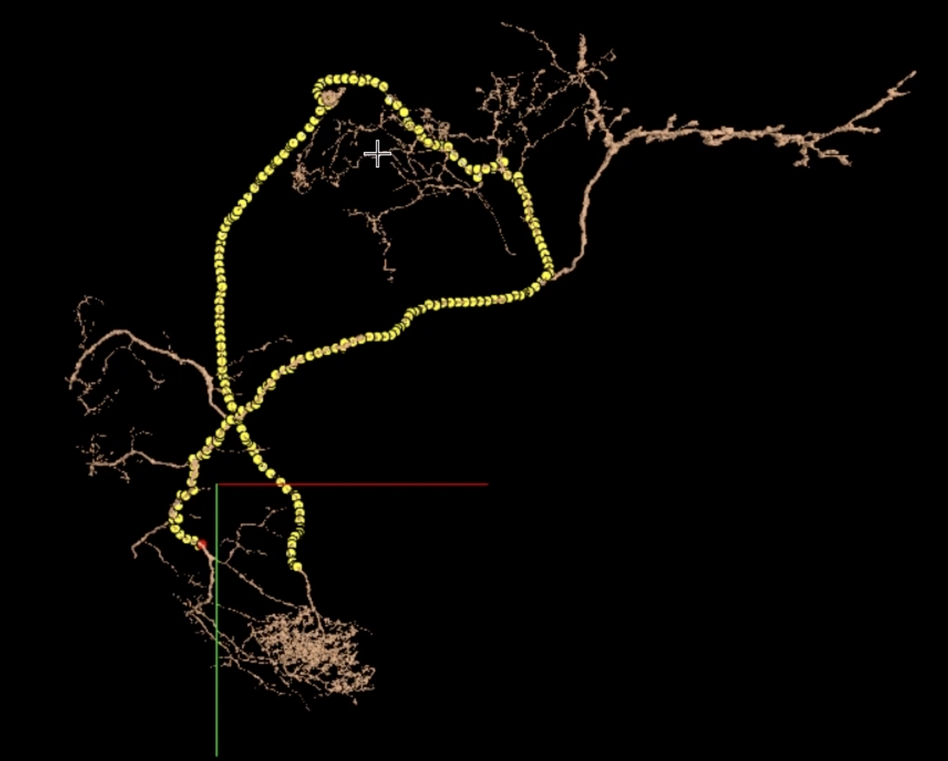
The phrase “fits the cell” should remain a hypothesis, not a substitute for image evidence. Some neurons have sparse, asymmetric, or unusual arbors. Use morphology to decide where to inspect more carefully, then return to the EM sections for the actual decision.
Read the sections on path swaps, overall arbor shape, and common merge geometries. They demonstrate why a local EM inspection should be paired with a broader 3D morphological review.
In “Identifying Path Swaps,” read the path-swap indicators. Focus on visual breaks and directionality, not cell-type guesses. Then read the “Gaps in Dendritic Arbors” passage from the whole-cell review. Finally, in the “X-Shaped Mergers” and “H-Shaped or Parallel Mergers” subsections, read the merger patterns, noting why parallel branches can have misleading or displaced apparent bridges.
Find Path: useful locator, not biological proof
Find Path is particularly helpful when the 3D reconstruction says two remote points belong to one selected root but you cannot locate the exact connection responsible.
Use it as an investigative tool:
- Choose a point on a known-good portion of the target cell.
- Choose a point on the suspiciously attached branch.
- Create the path and follow it in 3D until it narrows the likely attachment region.
- Return to 2D at that region and inspect consecutive sections.
- Remove the path once you have recorded or resolved the site.
The important logical boundary is this: Find Path confirms that the present segmentation graph provides some path between its selected points. That may expose the erroneous bridge in a false merge, but it cannot independently validate the connection. If the current segmentation is wrong, its path can faithfully display that wrongness.
For an H-shaped or parallel merge, the 3D overlap can make the apparent bridge deceptive. The path may lead to a different, less visually obvious bridge than the place where two branches seem nearest. This is why the sequence is valuable: use the path to locate the candidate bridge, then make the decision from EM continuity and separation.
A pre-edit verification protocol
Use the following protocol every time you are considering a merge or split. It is deliberately slower than “see suspicious shape, click tool,” because it prevents high-impact edits based on one misleading view.
1. State the claim
Classify the proposed operation before using an edit tool:
- Merge claim: two disconnected current segments are one biological process.
- Split claim: one current segment contains material from different biological processes.
Name the target root, candidate fragment or branch, and current location.
2. Establish a trusted starting point
Pick a short stretch of neurite that is unambiguously part of the target cell. Do not begin inside the ambiguous junction. Trace from trusted material toward the questionable area.
3. Scroll through the junction in both directions
Inspect consecutive sections before, at, and after the candidate site. Follow membranes and internal texture, not overlay color alone. If you encounter a misalignment or imaging defect, use a landmark to reorient; if you cannot recover the continuity, mark the case uncertain.
4. Test the counter-hypothesis
Actively ask what would make your first interpretation wrong.
For a proposed merge:
- Could the nearby fragment pass behind or beside the target branch?
- Is there a faint membrane separating them?
- Does one candidate change direction in a way inconsistent with the other?
For a proposed split:
- Could the apparent separation be a real branch point?
- Does a membrane truly divide the two regions?
- Is the segmentation bridge actually somewhere else along the path?
This step is essential because dense neuronal tissue often provides a plausible visual story for either interpretation.
5. Inspect 3D at local and global scales
At close range, look for a mesh pinch, unexpected intersection, or path discontinuity. Then zoom out to judge branch direction, arbor completeness, and the likely scope of the operation. Use Find Path where the current root’s bridge is difficult to locate.
6. Make one of three decisions
| Decision | Meaning | Appropriate action |
|---|---|---|
| Verified | 2D evidence and 3D morphology support the same biological interpretation. | Proceed to the appropriate edit workflow in the next lesson. |
| Needs more review | Some evidence supports the edit, but an image defect, unresolved crossing, or unclear bridge remains. | Save a share link or note; inspect further or seek review. |
| Rejected | Adjacent sections contradict the proposed merge or split. | Leave the reconstruction unchanged and record why. |
A well-documented unchanged decision is valuable proofreading work. It rules out an attractive but unsupported edit and preserves the reconstruction’s current state.
A compact evidence note before editing
Before committing a verified edit, write a concise pre-edit note. This creates a record you can compare with the post-edit morphology in the next lesson.
Use this format:
Location: dataset coordinates or a Share link
Proposed operation: merge / split
Objects: target root and candidate root or attached branch
2D evidence: what is seen across adjacent sections, including any membranes, continuity, or gap
3D evidence: morphology, route, branch direction, or Find Path observation
Confidence: verified / needs review / uncertain
Expected outcome: what should remain attached or detached after the edit
For example:
Proposed operation: split
2D evidence: Across consecutive sections around the candidate bridge, a membrane separates the target neurite from the attached branch; the overlay spans that separation.
3D evidence: The attached branch reverses the expected local direction and leads into a separate arbor; Find Path localizes the current bridge to this region.
Confidence: verified.
Expected outcome: the target arbor remains intact, while the incompatible branch becomes a separate root.
This level of specificity is more useful than “bad merge near branch.” It records the evidence needed to defend, reproduce, or reconsider the action later.
Key takeaways
- Treat the 2D EM imagery as the primary evidence for a biological continuation or separation.
- Verify a candidate site by tracing a process through adjacent sections in both directions.
- Inspect membrane boundaries, internal continuity, position, direction, caliber, and branch logic together.
- Use 3D reconstruction to test the global morphological consequences of the proposed decision and to spot gaps, anomalous attachments, and path swaps.
- Use Find Path to locate the current segmentation’s bridge, not to prove that the bridge is biologically correct.
- If image quality or alignment prevents a clear judgment, classify the case as uncertain rather than forcing an edit.
- Record the claim, evidence, confidence, and expected outcome before changing a root.
Next, you will apply this evidence protocol to a well-supported false split and carry out a merge safely, then inspect the result for unintended consequences.
Can't find a good explanation? Sign up and we'll make it for you
Sign up