
Welcome to Day 4. For the past three days, we have focused exclusively on the design and manufacturing of plastic components using injection molding, culminating in the formal documentation of an engineering change. Today, we pivot to a completely different, yet equally fundamental, area of automotive engineering: Sheet Metal Stamping. This process is the foundation of the vehicle's entire structure, the Body-in-White (BIW).
Just as we began with the fundamentals of the injection molding cycle, we will start this module by understanding the core manufacturing process. This lesson focuses on the sequential nature of stamping. Your goal is to describe the sheet metal stamping process stages (blanking, drawing, trimming, flanging) and their sequence. By the end of this session, you will understand how a simple, flat coil of steel or aluminum is transformed into a complex, three-dimensional automotive panel.
The Stamping Process: A Sequence of Operations
A complex automotive part like a door panel, fender, or floor pan cannot be formed in a single press stroke. Instead, the flat sheet metal progresses through a series of stations, each with a dedicated die that performs a specific operation. This sequence of operations is meticulously planned by manufacturing engineers to ensure the part is formed without defects.
To begin, let's get an overview of the key operations and see a real-world example of a process sequence for a car body side panel.
[PDF] DIE MANUFACTURING PROCESS - WebThesis - Politecnico di Torino
This document from a thesis at Politecnico di Torino provides an excellent, concise overview of the stamping operations used in the automotive industry.
Please read section 1.3 Stamping operations. Pay close attention to the list of common operations and the example sequence shown for the car body side (OP10 through OP70). This introduces the core vocabulary we will be using.
As you saw, the process is broken down into numbered operations (OP10, OP20, etc.). While the exact sequence varies depending on part complexity, the fundamental stages are consistent. Let's break down the four key stages from your learning outcome.
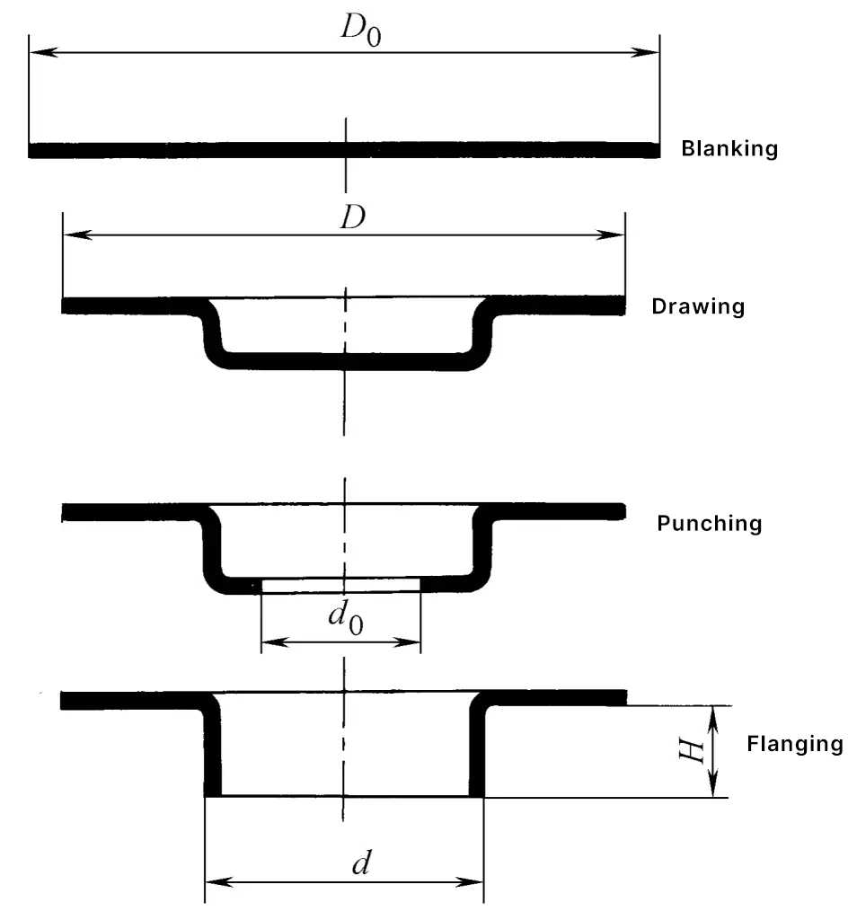
Stage 1: Blanking
Blanking is the first step in the process. It involves using a cutting die to shear a flat piece of metal, called a "blank," from a larger coil or sheet. This blank has the rough outline of the final part, plus additional material needed for the subsequent forming operations.
- Input: A coil of sheet metal.
- Process: A high-speed press with a cutting die cuts the 2D perimeter of the blank.
- Output: A stack of flat, shaped blanks ready to be fed into the main press line.
The design of the blank is critical for material utilization (nesting multiple blanks on a coil to minimize scrap) and for ensuring there is enough material for the drawing stage.
Stage 2: Drawing
Drawing is arguably the most critical forming operation. This is where the flat, 2D blank is transformed into a 3D part by forcing it into a die cavity with a punch. This process stretches and compresses the material to create features like the depth of a door panel or the shape of a fender.
- Input: A flat sheet metal blank.
- Process: The blank is placed over a die cavity. A "blank holder" or "binder" clamps the edges of the blank with immense force. A punch then descends, pushing the metal into the die cavity and plastically deforming it.
- Output: A 3D formed panel, with the desired depth and primary shape.
The mechanics of drawing are complex. To understand the forces at play and why features like a blank holder are essential, let's watch a detailed explanation.
Complete Guide to Sheetmetal Deep Drawing Die Punch Design Calculation
The channel Master Mechanical DESIGN provides a clear, animated guide to the deep drawing process. This will help you visualize what happens to the metal.
Please watch the section from sheet metal drawing. Focus on: How the punch and die create the shape. The two types of stress induced in the flange (radial drawing stress and tangential compressive stress). The role of the blank holder in preventing wrinkles, which is a major potential defect.
As you saw, controlling the material flow into the die is paramount. Too little restraint and the material wrinkles; too much restraint and it can tear. The force applied by the blank holder is one of the key process parameters controlled in the stamping plant.
Stage 3: Trimming
After drawing, the part has its basic 3D shape, but it is surrounded by excess material that was held by the blank holder. Trimming is a cutting operation that removes this unwanted material from the perimeter of the part.
Often, other cutting operations like piercing (punching holes for fasteners, wiring, etc.) are performed in the same or subsequent stations.
- Input: A 3D drawn panel.
- Process: The part is placed in a trimming die. Hardened steel blades in the upper and lower dies move past each other, shearing off the excess material.
- Output: A formed panel with a clean, defined perimeter and any necessary holes.
The document from Politecnico di Torino (LINK) describes trimming as an operation "applied to perimeter areas, on which the Blank holder has previously operated." This directly links the need for trimming back to the drawing process.
Stage 4: Flanging
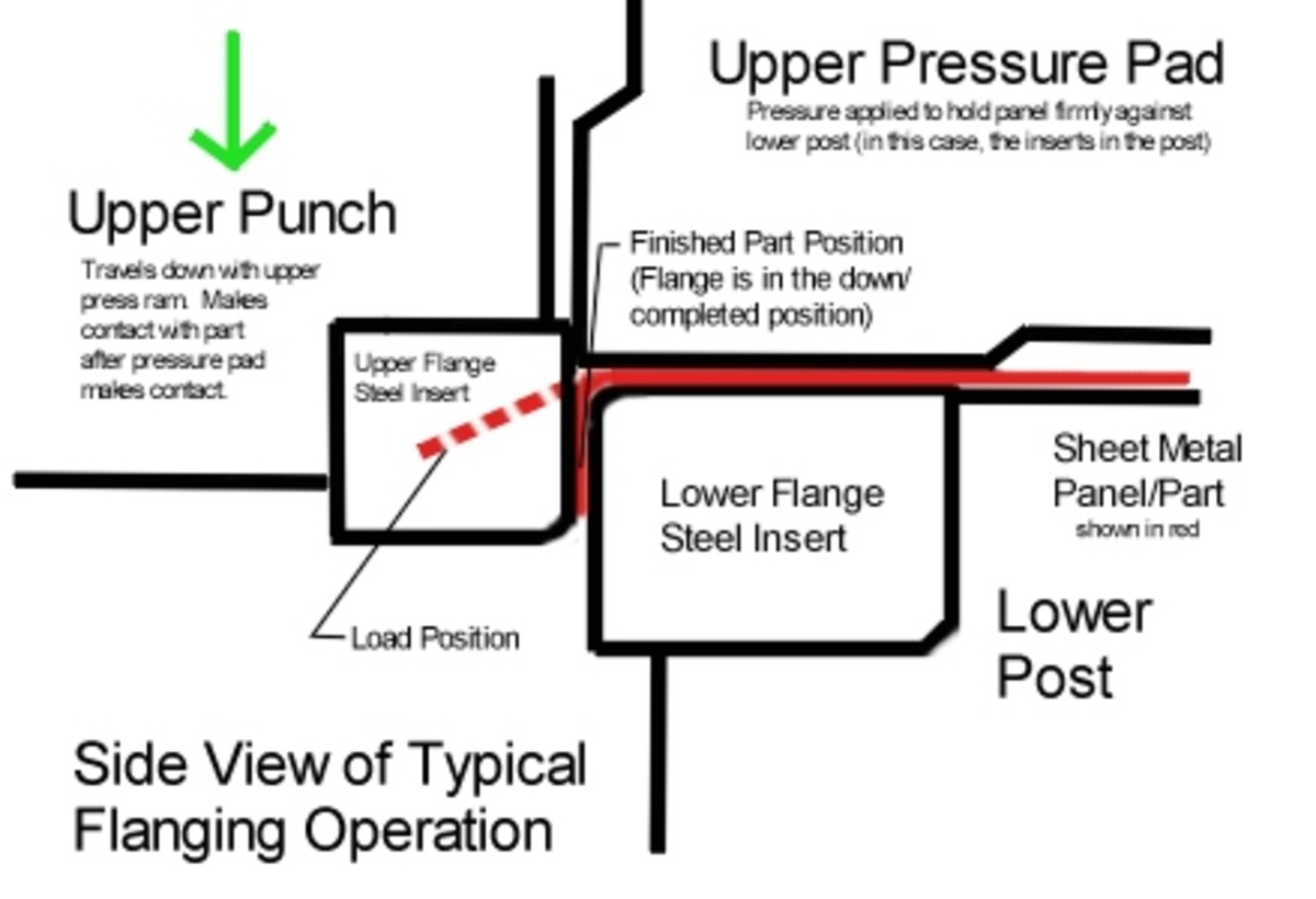
The final forming stage for many parts is flanging. This operation involves bending the edges of the panel, typically at a 90-degree angle.
- Input: A trimmed panel.
- Process: The panel is placed in a flanging die. Cams or direct-acting steel sections bend the edges of the sheet to a specified angle and radius.
- Output: A finished panel with stiffened edges, ready for assembly.
Flanges are critical for several reasons:
- Stiffness: A simple 90-degree flange dramatically increases the bending stiffness of a panel.
- Assembly: Flanges provide surfaces for spot welding, hemming (folding an edge over another panel), or attaching other components.
- Safety: They can create a smooth, rounded edge instead of a sharp, cut edge.
A Real-World Automotive Example
Now, let's tie these stages together with a concrete example from industry. This article discusses the process design for an aluminum hood outer panel.
Changan China: Methods to Improve Aluminum Panel Process Design
This case study from FormingWorld outlines the stamping process for a hood panel.
Read section 5.1 Basic Information of the Die. Pay close attention to Figure 11, which shows the "Stamping process layout."
The process layout for the hood provides a perfect summary:
- OP10 Draw: The first forming operation to create the hood's shape.
- OP20 Trim and Piercing: The excess draw-off material is cut away, and some holes are pierced.
- OP30 Trim: A second trimming operation, likely for more detailed areas.
- OP40 Flange and Trim: The final operation to bend the outer flanges of the hood and perform a final trim.
This sequence demonstrates the core logic: first form the deep shape (Draw), then cut away waste (Trim), and finally finish the edges (Flange).
Conclusion
In this lesson, we have dissected the fundamental workflow of sheet metal stamping. You now understand how a sequence of distinct manufacturing operations transforms a flat blank into a functional automotive component.
Key Takeaways:
- Sheet metal stamping is a sequential process, often denoted by operation numbers (OP10, OP20, etc.).
- Blanking is the initial cutting operation that creates the flat, 2D starting shape.
- Drawing is the primary forming operation that gives the part its 3D depth and shape, requiring a blank holder to control material flow and prevent defects.
- Trimming is a necessary cutting operation to remove the excess material used during the drawing process.
- Flanging is a final forming operation that bends the panel's edges to add stiffness and provide surfaces for assembly.
In our next lesson, we will build upon this process knowledge by examining the materials themselves. We will compare common automotive sheet metals (mild steel, HSLA, DP steel, aluminum) based on their strength and formability, properties which are in direct tension during the drawing process we just discussed.
Can't find a good explanation? Sign up and we'll make it for you
Sign up