
Welcome to Day 6, the final day of our intensive course. We've moved from injection molding fundamentals to the detailed design of a stamped bracket, culminating in the creation of its production drawing. That drawing represents a "released" design—a technical baseline. However, in the automotive world, no design is ever truly final. Today, we shift our focus from creating new designs to managing changes in existing ones, a critical skill for any lead engineer.
Our objective is to learn how to interpret an Engineering Change Order (ECO) for a multi-part Body-in-White (BIW) structural assembly. We'll dissect the formal change process, understand the key documents, and apply this knowledge to a real-world BIW redesign scenario. This will set the stage for our final, complex design task.
1. The Engineering Change Process
An Engineering Change (EC) is a formal modification to a component, assembly, or its related documentation after it has been released. Changes are driven by numerous factors: cost reduction initiatives, manufacturing feedback (DFM), quality improvements, new regulatory requirements, or customer-facing enhancements. Uncontrolled changes lead to chaos, so the process is rigorously managed.

The process begins with a request and ends with an order.
- Engineering Change Request (ECR) / Problem Report (PR): This document proposes a change. It identifies a problem or an opportunity and is submitted for review by a cross-functional team (engineering, manufacturing, purchasing, quality).
- Engineering Change Order (ECO) / Engineering Change Notice (ECN): If the ECR is approved, an ECO is created. This document authorizes the change. It is the official instruction that details exactly what needs to change, why, and when.
This workflow ensures that every change is properly vetted for its technical, financial, and logistical impacts before being implemented.
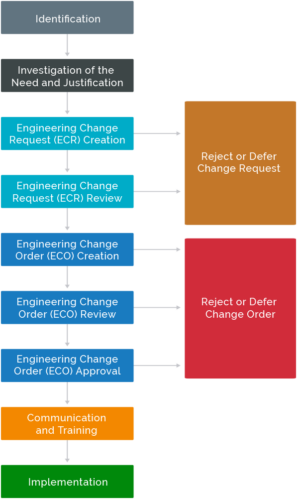
To understand this workflow and the associated documentation in a PLM (Product Lifecycle Management) environment like Teamcenter, please review the following resource.
Teamcenter Change Process and Workflows | Swoosh Technologies
This article from Swoosh Technologies provides an excellent overview of the terminology and structure of the engineering change process.
Focus on the definitions provided in the sections "What’s an Engineering Change Process?", "What’s a Workflow?", and "What is (a) Change (Process)?". Pay close attention to the distinction between a Problem Report (PR), Change Request (CR), and Change Notification (CN), which are analogous to the ECR/ECO terminology.
2. Anatomy of an ECO: A Practical Example
An ECO is a comprehensive document. As a design engineer receiving an ECO, you must be able to quickly extract the critical information needed to execute the change. Let's look at what's inside a typical ECO by following a practical example.
The resource we just reviewed provides a detailed walkthrough of an engineer initiating a change to a bracket due to a clearance issue. This example illustrates how the abstract forms and workflows are used in practice.
Teamcenter Change Process and Workflows | Swoosh Technologies
This section provides a concrete example of an ECO being processed in Teamcenter.
Read the section beginning with "Let’s look at an example in Teamcenter". Follow the steps taken by "Ed the engineer" as he: Identifies a clearance problem in an assembly. Creates an Engineering Order (EO). Marks up the drawing to visually define the requested change. Fills out the change form, summarizing the intent. Identifies the part revision to be made obsolete and the new revision to be created. Submits the change into a workflow for others to execute and approve. This example is a blueprint for how you will receive and interpret work. The marked-up drawing and the change summary are your primary instructions.
From this example, we can distill the key fields you'll find on most ECO forms:
- Identifying Information: ECO Number, Title, Change Initiator.
- Rationale: The "why." A clear problem statement (e.g., "Insufficient clearance of 6mm between bracket and actuator").
- Affected Items: A list of part numbers being changed. This includes the
Solution Item(the part being revised) andAffected Item(the assembly it belongs to). - Disposition: Instructions for existing inventory (e.g., "Scrap," "Rework," "Use As Is").
- Effectivity: The implementation point of the change (e.g., effective from a specific date or vehicle unit number).
- Change Description: The "what." A detailed summary of the modifications required.
- Attachments: The most important section for an engineer, containing marked-up drawings, sketches, new 3D models, or analysis reports.
3. Case Study: Interpreting a BIW Redesign ECO
Now, let's apply these concepts to a complex, multi-part BIW assembly. Imagine you are a BIW engineer, and you have just been assigned ECO-BAIC-0417, which calls for a significant redesign of the front-end middle pole structure. Your first task is to interpret the ECO package to understand its scope and rationale.
The following document is a technical paper that details the "before" and "after" of this redesign project. We will treat it as the technical attachment to our hypothetical ECO.
[PDF] redesign Middle pole structure of front end of BIW - DFMA® Software
This paper from the Beijing Automotive Technology Center documents a DFMA-driven redesign of a BIW structure. It perfectly encapsulates the kind of information you would find in an ECO package for a major change.
Read the following sections to interpret our ECO: "The problem of the original design": This section is the Rationale for the ECO. Identify the specific weaknesses and inefficiencies of the original multi-part steel assembly. "The redesign proposal": This is the Summary of Changes. Focus on the specific actions taken, such as part integration, material change, and fastener consolidation. "The comparison between original design and redesign": This section details the Impact of the change, quantifying the benefits in part count, assembly time, and quality.
4. Your Task: Deconstruct the ECO
Based on your review of the "Redesign of Middle Pole Structure" paper (LINK), you will now act as the receiving engineer and formally document your interpretation of ECO-BAIC-0417.
Provide short, bulleted answers to the following prompts, extracting the information directly from the case study paper.
- ECO Rationale: What were the top 3 problems with the original design that prompted this change?
- Summary of Changes: Describe the 3 most significant modifications made in the redesign.
- Key Impact Metrics: List 3 measurable improvements that resulted from implementing this ECO.
This exercise mirrors the real-world task of receiving an engineering change, digesting the technical data, and confirming your understanding before beginning any CAD work.
Conclusion
Today we have stepped back from pure design work to understand the critical process of managing change. As a senior engineer, a significant portion of your work will involve responding to, and creating, engineering changes.
Key Takeaways:
- Engineering changes are formally managed via a structured process involving ECRs (requests) and ECOs (orders).
- An ECO is a binding document that authorizes a change, clearly defining the what, why, and when.
- Interpreting an ECO means dissecting its components—the rationale, the list of affected parts, and the technical description—to build a clear picture of the required work. Our BIW case study showed how a cost/weight reduction initiative (DFMA) is a common driver for major ECOs.
In our next lesson, we will execute the change described in this ECO. You will be tasked with modeling the new multi-part BIW assembly, applying CATIA logic for creating sheet metal features like spot weld flanges and joints, as we bring this engineering change to life in CAD.
Can't find a good explanation? Sign up and we'll make it for you
Sign up