
Hello! Welcome to the final lesson in our module on Mechanical Vibrations.
In our last lesson, we investigated the steady-state response of a system to a continuous harmonic force. We derived the formulas for the magnification factor and phase lag , and saw that the amplitude of vibration can become very large when the forcing frequency gets close to the system's natural frequency .
Today's lesson centers on this critical phenomenon. Your learning outcome is to explain the concept of resonance and its significance in mechanical design. We will explore why resonance occurs, what limits its effects, and most importantly, how engineers design structures—from bridges to aircraft components—to handle this powerful behavior.
1. The Phenomenon of Resonance
In the previous lesson, we saw that the amplitude of steady-state vibration is given by:
where is the frequency ratio.
Resonance is the condition that occurs when the forcing frequency is equal or very close to the system's natural frequency (). At this point, the denominator in the equation above becomes very small, leading to a very large amplitude.
To see a clear explanation of resonance and its dramatic effects, please watch the following video segment.
Understanding Vibration and Resonance
This video from 'The Efficient Engineer' provides an excellent visual and conceptual introduction to resonance. It shows how the amplitude of vibration builds up and mentions some famous real-world examples.
Watch from 12:22 to 14:25. Focus on the relationship between the forcing frequency, natural frequency, and the resulting amplitude. Note the effect of damping on the peak amplitude.
As the video explains, resonance occurs because the timing of the applied force perfectly matches the natural "rhythm" of the system. Each push from the external force adds energy to the system precisely when it's ready to accept it, causing the amplitude of oscillation to grow with each cycle.
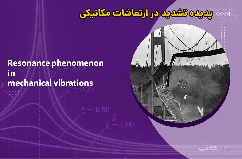
The most famous example of destructive resonance is the collapse of the Tacoma Narrows Bridge in 1940. Aerodynamic forces from the wind (vortex shedding) created a periodic forcing function that matched one of the bridge's natural frequencies, leading to catastrophic failure.
2. The Role of Damping and Phase at Resonance
What stops the amplitude at resonance from becoming truly infinite? As the video mentioned, the answer is damping.
Let's re-examine our key formulas at the exact point of resonance, where ():
-
Amplitude: The term becomes zero. The magnification factor simplifies to:
This simple but crucial result shows that the peak amplitude at resonance is determined solely by the damping ratio . Low damping can lead to extremely high amplitudes. -
Phase: The phase lag formula is . At , the denominator is zero. The argument of the arctan goes to infinity, which means:
At resonance, the displacement of the mass lags the applied force by exactly a quarter of a cycle. This means the force is at its maximum when the mass is passing through its equilibrium position () with maximum velocity. This is the most efficient condition for transferring energy into the system.
This behavior is analogous to a series RLC circuit at its resonant frequency. The impedance becomes purely resistive (), maximizing the current. Here, the mechanical response is maximized, limited only by the damping , which is analogous to electrical resistance .
The following video provides a more mathematical look at these two key characteristics of damped resonance.
Damped resonance | Lecture 28 | Differential Equations for Engineers
In this lecture segment, Professor Jeffrey Chasnov confirms our findings for the resonance condition. He explains the significance of the 90-degree phase shift and the inverse relationship between amplitude and damping.
Watch from 10:34 to 12:57. Focus on the two key takeaways he highlights: the phase relationship and the effect of the damping coefficient (\alpha) on the amplitude.
3. Significance in Mechanical Design
For engineers, resonance is usually a hazard to be designed around. The large amplitudes and associated high stresses can lead to a host of problems.
Structural Resonance: How to Mitigate it?
To understand the consequences of resonance, please read the following section from the SimScale blog.
Read the section titled 'Effects of Structural Resonance'. This will give you a clear list of the dangers engineers must prevent.
As you just read, the effects can range from reduced performance and noise to catastrophic structural fatigue and component failure. So, how do engineers prevent this?
The primary strategy is frequency separation. The goal is to ensure that a structure's natural frequencies are far away from any significant forcing frequencies it will encounter during operation. This could include vibrations from an engine, aerodynamic forces, or even foot traffic on a bridge.
A common guideline used in industry is the "factor of 2 rule".
Resonance and the Factor of 2 Rule
This article from Vibration Research provides an excellent, practical overview of this design rule and its application, including examples relevant to your interests.
Please read the following sections: 'Avoiding Resonance in Design' and 'Factor of 2 Rule' (the two subsections under the main heading). The second 'Factor of 2 Rule' section, which includes a great example about an aircraft wing. The sections 'Math of Factor of 2 Rule' and 'Numerical Example' to see the quantitative justification for the rule. Notice how it uses the same frequency response function from our previous lesson.
The article you just read demonstrates the practical importance of this topic. By ensuring or , engineers create a safety margin that drastically reduces the amplitude of vibration. The numerical example shows that for a lightly damped system, moving the forcing frequency to just twice the natural frequency reduces the response amplitude to only ~3% of its value at resonance.
Your electronics background is also relevant here. The article "Resonance and the Factor of 2 Rule" also contains a section on "Circuit Card Example," which discusses how these same principles apply to ensuring electronic components on a circuit board don't fail due to vibration, a critical concern in aerospace and automotive applications.
Test your understanding!
An auxiliary power unit (APU) on an aircraft is mounted on a support structure. The APU has a mass of 100 kg and rotates at a constant speed of 6,000 RPM. You are designing the support structure. To be safe, your design must ensure the natural frequency of the APU-support system is not within the range defined by the "factor of 2 rule" relative to the APU's operating frequency.
- Calculate the primary forcing frequency in rad/s from the APU's operating speed.
- Determine the "forbidden" range of natural frequencies for the support structure, according to the factor of 2 rule.
- If you design the support to have a natural frequency above the forbidden range, what is the minimum stiffness the support structure must have?
Show answer
-
Forcing Frequency:
-
Forbidden Range for :
The factor of 2 rule states that the natural frequency should be outside the range .- Lower bound: rad/s
- Upper bound: rad/s
The forbidden range for is approximately 314 rad/s to 1257 rad/s.
-
Minimum Stiffness:
To be above the forbidden range, we must have rad/s. The relationship between natural frequency, stiffness, and mass is . We can solve for the minimum stiffness .
The support structure must have a stiffness of at least 157.9 MN/m to safely avoid resonance.
Conclusion
This lesson concludes our journey into mechanical vibrations. We have seen how the simple mass-spring-damper model can reveal incredibly important and powerful behaviors that are fundamental to engineering design.
Key Takeaways:
- Resonance is the tendency of a system to oscillate with maximum amplitude when the frequency of an applied force matches the system's natural frequency ().
- The amplitude at resonance is inversely proportional to the damping ratio (), highlighting the critical role of damping in controlling vibrations.
- At resonance, the system's displacement lags the forcing function by 90 degrees, the optimal condition for energy transfer.
- The consequences of unintended resonance include noise, poor performance, structural fatigue, and catastrophic failure.
- In mechanical design, the primary strategy to mitigate resonance is frequency separation, often guided by practical rules of thumb like the factor of 2 rule.
Next Steps:
We have now completed our study of the mechanics of rigid and deformable solids. We've covered statics, strength of materials, and dynamics. In the next module, we will shift our focus to another fundamental pillar of mechanical and aerospace engineering: Fluid Mechanics. We will begin by defining the basic properties of fluids and understanding the pressures they exert when at rest.
Can't find a good explanation? Sign up and we'll make it for you
Sign up