
In our last lesson, we explored the art of simplifying Boolean expressions using algebraic laws. This powerful technique helps us design more efficient circuits. But how can we be absolutely certain that our simplified expression behaves identically to the original, more complex one? And how do we even begin to describe the desired behavior of a circuit in the first place?
This lesson introduces the truth table, a fundamental tool in digital logic that provides a complete and unambiguous definition of a logic function. We'll move from the abstract manipulation of algebra to a systematic, exhaustive method for describing and verifying circuit behavior. By the end of this lesson, you will be able to construct a truth table for any given combinational logic expression or circuit diagram, and interpret what that table tells you about the circuit's function. This is the "ground truth" upon which more advanced design and optimization techniques are built.
What is a Truth Table?
A truth table is a straightforward concept: it's a table that lists every possible combination of input values for a logic function and shows the resulting output for each combination. For a function with inputs, the table will have rows, covering all possibilities. It is the ultimate specification for a combinational logic circuit, leaving no room for ambiguity.
The article "Truth Table" from GeeksforGeeks provides a solid introduction to the concept and the steps to create one.
This article clearly defines what a truth table is and outlines the systematic procedure for its construction.
Please read the first two sections, What is Truth Table? and How to Create a Truth Table. Focus on the three key steps: identifying variables, determining the number of rows (2^n), and listing the combinations.
Constructing a Truth Table: A Step-by-Step Guide
The process of building a truth table is methodical. Let's formalize the steps:
- Identify Inputs and Outputs: List all input variables in columns on the left and the final output variable in a column on the right.
- Determine the Number of Rows: Calculate , where is the number of inputs. This tells you how many unique input combinations exist. For 3 inputs (A, B, C), you'll have rows. For 4 inputs, rows.
- List All Input Combinations: Fill the input columns with every possible binary combination, from 0...0 to 1...1. A common and error-free way to do this is to count up in binary.
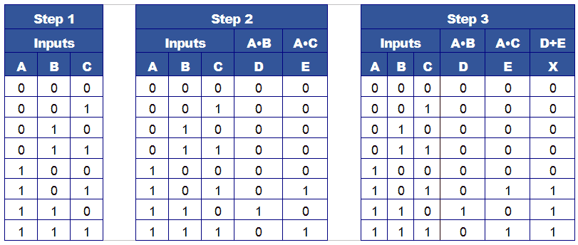
- Add Intermediate Columns: For any complex expression, it is extremely helpful to break it down. Create new columns for the outputs of intermediate gates or sub-expressions.
- Calculate Outputs: Work from left to right, filling in the intermediate columns based on their inputs, until you can calculate the final output for each row.
The following image perfectly demonstrates this process for the expression . Notice how the problem is broken down into smaller, manageable steps.
From Logic Circuit to Truth Table
The same systematic process applies when you start with a circuit diagram instead of a Boolean expression. You identify the inputs, label the outputs of each gate as intermediate points, and build the truth table column by column.
The following video from ElectronicsTeaching provides an exceptionally clear and detailed walkthrough of this exact process. The instructor's method of labeling intermediate points (X, Y, Z) and creating a column for each is a critical technique to adopt.
Logic Circuit Analysis using Truth Tables
This video methodically demonstrates how to analyze a logic circuit and generate its complete truth table by breaking it down into smaller parts.
Watch the entire video from start to finish. Pay close attention to how the presenter: Lists all input combinations systematically (Input Combinations). Identifies intermediate points in the circuit and adds columns for them in the table (Intermediate Columns). Evaluates each intermediate column one by one by referring to the truth tables of the basic gates (Evaluating Stages). Calculates the final output Q using the results of the intermediate columns (Final Output).
To reinforce this process, the next video from Engineers Academy provides two more excellent examples. It also introduces a useful trick called the "half and half rule" for quickly generating the input combinations.
Constructing Truth Tables for Combinational Logic Circuits
This video offers two more worked examples of creating truth tables from combinational circuits and presents a handy method for listing the input patterns.
First, watch the explanation of the "half and half rule". This is a great shortcut for correctly listing all 2^n input combinations without having to meticulously count in binary. Then, follow along with the first example (AND-OR circuit) and the second example (XOR-NAND circuit). Notice how the use of an intermediate column P simplifies the problem.
Interpreting and Using Truth Tables
Now that you can construct a truth table, what do you do with it?
1. Verifying Simplification:
In the previous lesson, we used Boolean algebra to simplify to . A truth table can prove they are equivalent. Let's build a table for both.
| A | B | (Original) | (Simplified) | ||
|---|---|---|---|---|---|
| 0 | 0 | 1 | 0 | 0 | 0 |
| 0 | 1 | 1 | 1 | 1 | 1 |
| 1 | 0 | 0 | 0 | 1 | 1 |
| 1 | 1 | 0 | 0 | 1 | 1 |
Since the final output columns are identical for all input combinations, we have formally proven that the simplification is correct. The two circuits are functionally equivalent.
2. Deriving a Boolean Expression:
You can also work in reverse—from a truth table to a Boolean expression. The standard method for this is called the Sum-of-Products (SOP) form. You simply:
- Identify every row where the output is
1. - For each of those rows, write an AND term (a "minterm") that is only true for that specific input combination.
- OR all of these AND terms together.
This process guarantees you can create a logic expression (and thus a circuit) for any truth table. We will explore a more efficient way to do this in the next lesson.
Practice Exercise
Let's put your new skills to the test. Your goal is to determine the complete truth table for the logic circuit shown below, finding the final output Q.

Use the systematic approach we've just covered. I recommend the following columns for your table:A, B, C, X = A OR B, Y = NOT C, Z = A OR Y, Q = X AND Z
Take a moment to draw the table and fill it out yourself before revealing the solution below.
Click to see the completed truth table
| A | B | C | X = A OR B | Y = NOT C | Z = A OR Y | Q = X AND Z |
|---|---|---|---|---|---|---|
| 0 | 0 | 0 | 0 | 1 | 1 | 0 |
| 0 | 0 | 1 | 0 | 0 | 0 | 0 |
| 0 | 1 | 0 | 1 | 1 | 1 | 1 |
| 0 | 1 | 1 | 1 | 0 | 0 | 0 |
| 1 | 0 | 0 | 1 | 1 | 1 | 1 |
| 1 | 0 | 1 | 1 | 0 | 1 | 1 |
| 1 | 1 | 0 | 1 | 1 | 1 | 1 |
| 1 | 1 | 1 | 1 | 0 | 1 | 1 |
By the way, using the distributive law from our last lesson, you can see that . You can verify this simplified expression yields the same truth table!
Conclusion
In this lesson, we established the truth table as the definitive specification for any combinational logic function. It provides a methodical and exhaustive way to analyze, define, and verify the behavior of digital circuits.
Here are the main takeaways:
- A truth table lists all possible input combinations () and the corresponding output for a logic function.
- The construction process is systematic: list inputs, generate all binary combinations, use intermediate columns to evaluate sub-expressions, and work your way to the final output.
- Truth tables are essential for verifying algebraic simplifications by proving that two different expressions produce identical outputs for all inputs.
- They serve as the starting point for generating a Boolean expression from a functional description, a concept known as the Sum-of-Products.
While truth tables are perfect for defining a function, they don't inherently make it simpler. In our next lesson, we will learn about Karnaugh maps (K-maps), a brilliant graphical method that uses the information from a truth table to help us find the simplest possible Boolean expression for a given function.
Can't find a good explanation? Sign up and we'll make it for you
Sign up