
Hello! Welcome to the final lesson in the module on Torsion and Bending in Beams.
In our previous lesson, we learned how to use the flexure formula, , to analyze a given beam and calculate the maximum stress it experiences under a load. This is a crucial skill for verifying if an existing design is safe.
Today, we're going to approach the problem from the opposite direction, which is more typical of a design scenario. We will start with a known load and a chosen material, and our goal will be to select the most suitable beam to carry that load safely and efficiently. This lesson addresses the learning outcome: Determine maximum bending stress and select appropriate beam sections for strength.
For your aerospace engineering goals, this process is fundamental. When designing an aircraft structure like a wing spar, engineers must select a cross-sectional shape that can withstand the aerodynamic bending loads while being as lightweight as possible. This lesson will introduce you to the core principles behind that selection process.
1. From Analysis to Design: The Section Modulus
Our journey starts with the flexure formula for maximum stress, which you're now familiar with:
In a design context, the goal is to ensure that the maximum stress experienced by the beam () does not exceed a certain allowable stress () for the material. The allowable stress is determined from the material's inherent strength (e.g., its yield strength) and a factor of safety.
So, our design condition is:
Substituting the flexure formula, we get:
Since our goal is to choose the beam's geometry, we can rearrange this inequality to group all the geometric terms on one side:
This brings us to a very important design parameter.
The Section Modulus,
The term depends only on the shape and size of the beam's cross-section. It is called the section modulus and is denoted by the letter .
- is the area moment of inertia about the neutral axis.
- is the distance from the neutral axis to the outermost fiber of the beam.
The section modulus represents a beam's efficiency in resisting bending. A larger section modulus means the beam can withstand a greater bending moment for the same amount of material stress.
With this new term, our design equation becomes beautifully simple:
This formula is the heart of beam design for strength. It tells us the minimum section modulus our beam must have to support the maximum bending moment without exceeding the material's allowable stress.
To see a concise explanation of how the section modulus is derived from the flexure formula, watch the following short video clip.
Understanding Stresses in Beams
This clip from 'Understanding Stresses in Beams' by The Efficient Engineer clearly shows how the section modulus (S) naturally arises from the flexure formula when considering maximum stress.
Watch from 4:00 to 5:29. Focus on how the terms I and y_max (which we call 'c') are combined to form the section modulus, S.
2. The Beam Design and Selection Process
Now that we have our core design equation, how do we use it in practice? Engineers rarely design beams with arbitrary dimensions. Instead, they select from a catalog of standardized shapes (like I-beams, hollow tubes, etc.) that are readily manufactured. These catalogs provide all the necessary geometric properties, including the all-important section modulus, .
The process generally looks like this:
- Analyze the Loads: Determine the maximum bending moment, , from the shear and moment diagrams.
- Determine Allowable Stress: Choose a material and a factor of safety to find .
- Calculate Required Section Modulus: Use the design equation .
- Select a Beam: Consult a beam properties table and find the lightest standard shape that has a section modulus greater than or equal to .
The following video provides an excellent walkthrough of this entire process.
This video, 'Beam Design' by Todd Fantz, will guide you through the practical steps of selecting a standard steel I-beam.
Please watch from 0:24 to 14:01. The video is broken down into key stages: The Design Formula (0:24 - 2:43): This part reinforces how we arrive at the required section modulus formula, S = M / σ_allowable. Using Beam Tables (2:43 - 8:43): Pay close attention to how standard beams are named (e.g., 'W6x12') and how to find the section modulus (Sxx) in the tables. Worked Example (8:43 - 14:01): Follow the step-by-step example of calculating an S_required value and then using the tables to find the lightest, most efficient beam that meets the requirement.
Key Concepts from the Video
- Beam Nomenclature: A "W-beam" is a wide-flange I-beam. A designation like W6x12 means:
- W: Wide-flange shape.
- 6: The nominal depth is approximately 6 inches.
- 12: The weight is 12 pounds per linear foot.
- The Goal of Efficiency: When multiple beams meet the strength requirement (), the engineering preference is to choose the one with the lowest weight. This minimizes material cost and, in applications like aerospace, is critical for performance.
Test your understanding!
In the video example, a W360x33 beam and a W310x33 beam were both identified as potential candidates because they met the required section modulus and had the same weight (33 kg/m). The presenter chose the W360x33. Why might a deeper beam (360mm vs 310mm) be a slightly better choice if the weight is identical?
Show answer
The presenter chose the W360x33 because it had a slightly larger section modulus ( mm³) compared to the W310x33 ( mm³). For the exact same weight and cost, it provides a slightly higher margin of safety against bending failure. Deeper beams are generally more efficient at resisting bending.
3. A Practical Example: Designing a Chinning Bar
Let's apply this process to a different shape. The following document outlines the design of a simple chinning bar, which we can model as a simply supported beam. This example is excellent because it starts from a real-world problem statement and includes material selection and safety factors.
Bending: Design for Strength, Stiffness and Stress ...
This document, 'Bending: Design for Strength, Stiffness and Stress ...', contains a great example of designing a chinning bar. We will focus on the strength design portion.
Read through the 'Example BD1' on pages 3 and 4. You don't need to follow every single calculation, but focus on understanding the design process outlined in steps 1 through 5: Material & Allowable Stress: Note how they choose a material (aluminum) and use a factor of safety (FS=1.2) to calculate the allowable stress from the material's yield strength. Loading: They simplify the problem by modeling a 270 lb person as a concentrated load at the center of the bar. Maximum Moment: They calculate M_max for this loading scenario. Strength Design: This is the key step. They use the design equation to find the required geometry. Since the cross-section is a hollow tube, they use the section modulus formula for that shape to solve for the required wall thickness.
In this example, instead of picking a shape from a table, the known variable was the outer diameter, and the unknown was the required wall thickness. After calculating the required thickness, an engineer would then check catalogs for standard pipe or tube sizes that meet or exceed this requirement, just as we did with the I-beam.
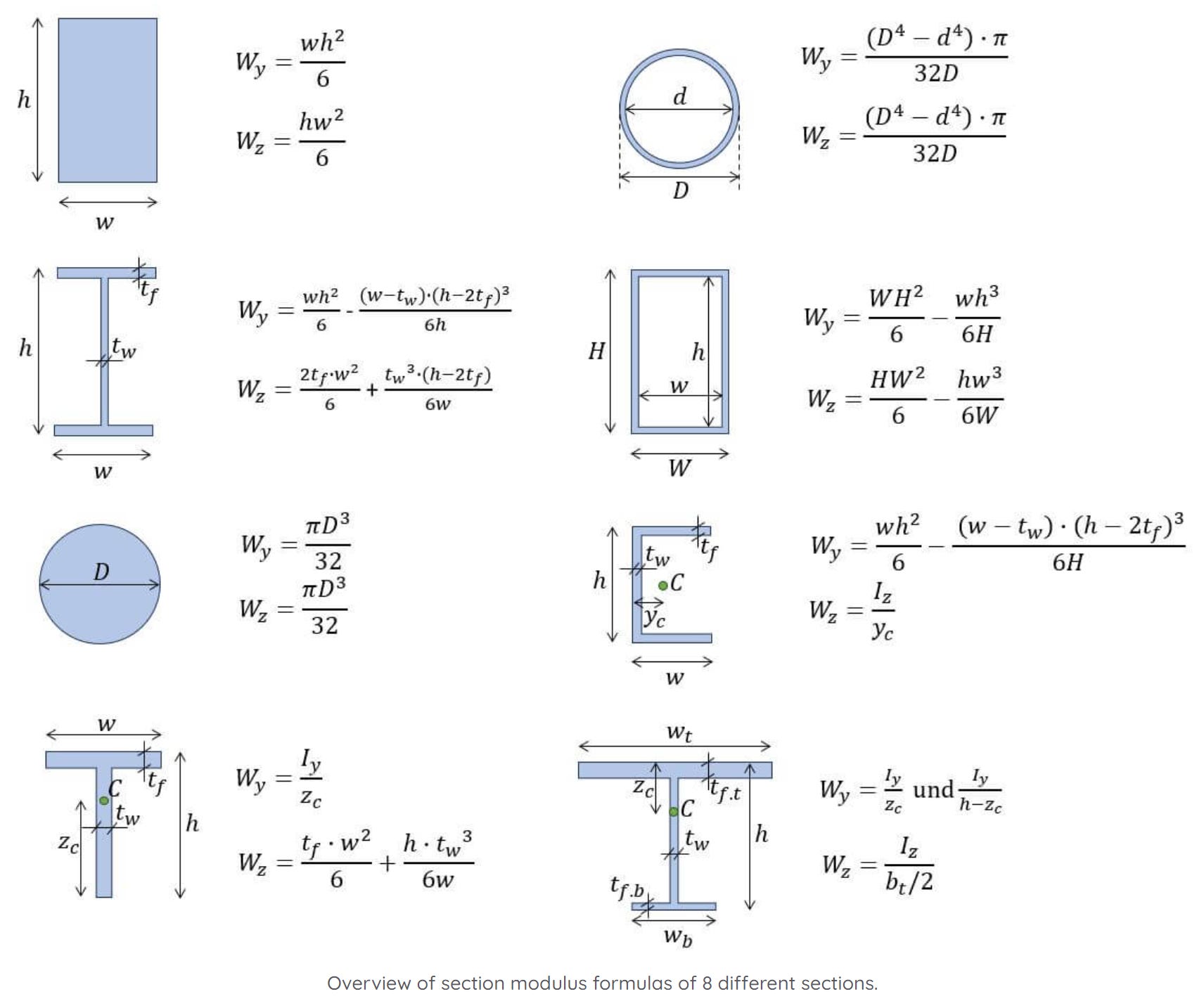
For your reference, here are the section modulus formulas for several common shapes. Having these handy is very useful.
4. A Note on Other Failure Modes
Our focus has been on designing for bending strength. However, a complete design must also consider other factors. As mentioned in the "Beam Design" video, the selected beam should also be checked to ensure it can handle the maximum shear force.
As a final point of practical interest, let's briefly revisit the 'Beam Design' video to see how a quick shear check is performed.
Watch from 14:01 to 16:56. Notice that for I-beams, a simplified check is often used where the average shear stress in the web ( au_{avg} = V_{max} / A_{web}) is compared to the allowable shear stress. This demonstrates that design is often an iterative process of checking against multiple criteria.
This check ensures the beam won't fail due to shear, which can be critical in short, heavily loaded beams. In the next module, we will also explore another crucial design criterion: deflection (stiffness).
Conclusion
In this lesson, you've transitioned from analyzing a beam's stress to designing a beam for strength. This represents a critical step in applying mechanics of materials to solve real-world engineering problems.
Key Takeaways:
- The goal of beam design for strength is to ensure the maximum bending stress does not exceed the material's allowable stress.
- The section modulus () is a geometric property that measures a cross-section's efficiency in resisting bending.
- The primary design formula is .
- The typical design process involves calculating and then selecting the lightest standard beam from a table that meets this requirement.
- Bending stress is often the dominant design criterion, but other factors like shear stress and deflection must also be considered.
Next Lesson Preview:
You now know how to select a beam that is strong enough to not break under a load. But what if it sags too much? In many applications, particularly in precision machinery and aerospace, controlling how much a beam deflects is just as important as controlling the stress. In the first lesson of our next module, you will learn to calculate beam deflections and slopes using standard formulas and the principle of superposition.
Can't find a good explanation? Sign up and we'll make it for you
Sign up