
Welcome back. In the previous lesson, you converted an informal component brief into atomic, measurable “shall” requirements and learned not to disguise assumptions or design decisions as approved inputs. This lesson adds the control mechanism that makes those requirements actionable: the requirements traceability matrix, or RTM.
For the assumed EDV projects, the RTM will connect each requirement to a planned way of proving compliance, an explicit pass condition, a responsible owner, and—eventually—the controlled evidence that closes the requirement. It is the thread that will later connect requirements to CAD, drawings, simulation, mold-flow reviews, DVP&R records, supplier evidence, PPAP-readiness material, and engineering changes.
The RTM: a requirement is not complete until its proof is planned
A requirement says what the component shall achieve. A traceability matrix records the chain of reasoning and evidence that lets the team show it has achieved it.
At minimum, the chain must preserve four distinct items:
- The requirement — the approved obligation and its source.
- The verification method — inspection, analysis, demonstration, test, or a justified combination.
- The acceptance criterion — the measurable condition for a pass.
- The evidence record — the controlled report, drawing, analysis, procedure, or other artifact that documents the result.
A useful RTM does not merely place “Test” beside a requirement. It makes the verification event executable. Someone should be able to determine:
- exactly what is being checked;
- on which configuration of the part or assembly;
- in what environment and condition;
- using which procedure, fixture, calculation, or inspection equipment;
- against which numerical, visual, or document-controlled pass criterion;
- who owns the evidence and when it is expected;
- whether the evidence is planned, in progress, passed, failed, waived, or superseded.
The NASA requirement-assurance model uses a Verification Matrix to hold this pre-verification information, then connects the planned information to closure documentation after the verification event. The terminology differs across companies, but the engineering intent is directly useful for an automotive program.
Requirement Assurance: A Verification Process
Read the relevant parts of NASA's Requirement Assurance: A Verification Process. Although its examples are aerospace-specific, its treatment of verification planning, success criteria, and closure evidence transfers well to controlled automotive component development.
In Section 3.2.1, “Verification Matrix,” read from the definition of the matrix through the discussion of what it establishes. Focus on the idea that the matrix is planned evidence, not a retrospective list of tests. Then move to Section 3.2.2, “Verification Compliance Sheet,” and Section 3.3, “Product Verification Execution.” Read the closure process. Notice the distinction between planning a verification event and approving objective evidence after it has actually occurred.
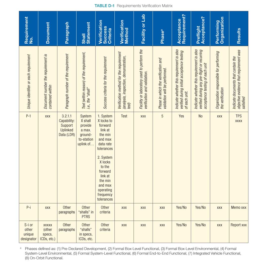
NASA’s matrix is deliberately detailed. The column headings in the image below show the maturity of a serious verification record: source location, requirement text, success criteria, method, facility, phase, acceptance status, responsible organization, and results. Your course RTM can begin in a spreadsheet, but it should preserve this logic.
The most important distinction is this:
| Field | Meaning | Example |
|---|---|---|
| Requirement | What must be true of the product | “The ECU enclosure assembly shall meet the approved installed ingress-protection target.” |
| Verification method | How compliance will be assessed | Test |
| Verification procedure or scope | The controlled activity to be performed | Mounted enclosure, declared orientation, specified conditioning, water-exposure sequence, post-test inspection |
| Acceptance criterion | What constitutes passing | No water in the protected volume and all specified functional checks pass |
| Result | What actually happened | No water observed; functional checks passed; report reference recorded |
Do not use a result as an acceptance criterion. “Test passed” is a status, not a criterion. Likewise, “verify IP67” is not a complete procedure or a usable pass condition until the applicable code, test setup, conditioning, configuration, and post-test checks are declared.
Traceability is a network, not just a spreadsheet
The word matrix can make the RTM sound like a flat table. In practice, traceability is a network of controlled relationships.
One stakeholder need may generate several component requirements. One requirement may affect multiple CAD features, drawing controls, or purchased parts. A single test event may produce evidence for several requirements, while a critical requirement may need both a development analysis and a physical test before release.
For example, the need to “protect the ECU electronics from vehicle exposure” may lead to separate requirements for:
- water ingress;
- dust ingress, if applicable;
- thermal cycling;
- chemical exposure;
- vibration survival;
- electrical isolation;
- enclosure retention and sealing integrity.
These should not be collapsed into one broad row called “environmental test.” Each has its own source, condition, failure mode, and acceptance condition.
Likewise, a gasket-compression requirement may be supported by several evidence types:
- a tolerance-stack analysis during design development;
- a CAD inspection of groove and compression-stop geometry;
- a supplier gasket-data review;
- a physical sealing test on representative hardware.
The RTM must make clear which of these activities are risk-reduction checks and which one is the release-closing verification. An early CAD check can support confidence; it does not automatically replace the final verification required by the product specification.
The following short segment reinforces why requirements should be mapped to the implementation and why that mapping supports auditing, design completeness, and verification planning.
An Introduction to Requirements | Systems Engineering, Part 4
Watch “An Introduction to Requirements | Systems Engineering, Part 4” from MATLAB. This segment connects allocated requirements, the chosen implementation, and the verification work that follows.
Watch traceability mapping. Focus on the three practical benefits: checking that design work addresses every requirement, confirming that each design element has a rationale, and deriving verification activities from the requirements.
For your simulated EDV program, preserve at least these trace links:
| Link | Why it matters |
|---|---|
| Source to requirement | Shows why the requirement exists and which revision of the source was interpreted. |
| Parent need to child requirement | Demonstrates that lower-level detail supports a legitimate vehicle or customer need. |
| Requirement to verification ID | Prevents requirements from being omitted from the validation plan. |
| Requirement to design implementation | Connects an obligation to a CAD feature, interface, drawing characteristic, or selected component. |
| Requirement to DFMEA or risk | Shows which failures were anticipated and what control or test addresses them. |
| Verification ID to evidence | Enables an auditor or reviewer to find the actual report, data, and configuration. |
| Evidence to release baseline | Proves which CAD, drawing, BOM, material, and sample revision was verified. |
The RTM is therefore both a planning tool and a change-control tool. When a gasket-land dimension, material, mounting interface, or test target changes, you can identify which requirements, tests, risks, drawings, and prior evidence need review.
Choose a verification method that can genuinely prove the requirement
You encountered the four basic verification methods in the first lesson. Here, the issue is selecting one that produces convincing evidence for the particular requirement.
| Method | Best used when | ECU-housing example | Common mistake |
|---|---|---|---|
| Inspection | Compliance can be determined by examining a controlled item, document, or measurement record | Inspect drawing callouts, molded-part dimensions, marking, or draft-analysis output | Calling a quick visual CAD review “inspection” without a defined criterion or controlled revision |
| Analysis | A calculation or simulation can represent the condition adequately | Tolerance stack for gasket compression; mass-properties check; shock-load FEA | Treating an uncorrelated analysis as proof when a physical test is required |
| Demonstration | The relevant evidence is successful observable operation | Demonstrate connector-latch access with the approved service-tool envelope | Calling an informal assembly attempt a demonstration without defined configuration and pass criteria |
| Test | Physical exposure, measured performance, or durability must be demonstrated | Ingress, vibration, thermal-cycle, chemical-resistance, or mechanical abuse testing | Writing “test to standard” without identifying the applicable procedure, sample, orientation, and acceptance condition |
The verification method is not selected by convenience. Select the method that makes the required claim credible.
For instance:
- The mass allocation of an enclosure can initially be assessed by CAD mass properties, then finally verified by weighing a representative physical assembly.
- The ability to fit within a controlled package can be verified by CAD interference analysis against a released interface model, then may be confirmed at a vehicle or buck build.
- The ability to survive an ingress exposure generally needs physical test evidence; a CAD review of the gasket groove is valuable but does not prove sealing performance.
- Connector service access often benefits from both digital mock-up and a physical demonstration with the intended tool and user condition.
A strong RTM can therefore list more than one verification activity for the same requirement. Give each activity a unique verification ID and state its role, such as:
- design-development analysis;
- design-verification test;
- production-intent confirmation;
- compliance inspection;
- release-closing verification.
This avoids a common failure mode: a promising early simulation is recorded as “Pass,” then mistakenly treated as final qualification evidence.
Build the matrix in two connected levels
A single giant spreadsheet can become difficult to review and easy to corrupt. For the course projects, use a simple two-level structure.
1. Requirements register: one row per requirement
Your existing Component Brief and Requirements tab remains the authoritative list of requirements. Each requirement retains one stable ID, such as ECU-ENV-001.
Recommended fields include:
| Requirement-controlled field | Purpose |
|---|---|
| Requirement ID and revision | Stable identity and current wording |
| Parent need / source ID | Upward traceability |
| Source document, clause, and revision | Exact origin of the obligation or assumption |
| Requirement statement | Atomic “shall” statement |
| Category and owner | Sorting and responsibility |
| Requirement maturity | Draft, under review, approved, superseded, or obsolete |
| Assumption / issue reference | Visible uncertainty and closure need |
| Allocated item or interface | Base, cover, gasket, vehicle mount, connector interface, and so on |
2. RTM or verification-plan tab: one row per requirement–verification pairing
The RTM contains the verification plan and later its result. A requirement with two meaningful verification activities therefore has two linked rows using the same requirement ID and different verification IDs.
Recommended columns are:
| RTM field | What to record |
|---|---|
| Requirement ID and revision | The exact requirement configuration being verified |
| Verification ID | Unique identifier, such as VFY-ECU-ENV-001-T01 |
| Verification role | Development evidence, design-verification evidence, release closure, or production confirmation |
| Method | Inspection, analysis, demonstration, test, or combination |
| Verification scope / procedure | Configuration, setup, procedure reference, sequence, environment, and measured characteristics |
| Acceptance criterion | Explicit pass condition, including units, limits, defect definition, or reference to a controlled criterion |
| Verification level | Prototype, tooling trial, production-intent, or other approved maturity level |
| Sample quantity and selection | Number of samples, sampling logic, and identification |
| Facility and owner | Test location or analysis owner; responsible function |
| Planned timing | Target event or program gate |
| Evidence artifact | Report, calculation, inspection record, as-run procedure, photographs where appropriate, and their revisions |
| Result and status | Planned, in progress, pass, fail, open nonconformance, waived, or superseded |
| Change / issue link | Nonconformance, deviation, supplier 8D, or ECO reference where needed |
A matrix with these fields is broad enough to support automotive work without pretending that a spreadsheet is a full requirements-management system. Later, the same identifiers and relationships can be represented as managed objects and links in an ENOVIA-style PLM environment.
A practical ECU-housing RTM example
The entries below are course assumptions for an assumed vehicle program. They are not claims about a Rivian-built Amazon EDV, an approved customer specification, or a supplier test requirement. Items marked [TBD] cannot be treated as release-ready until their source and value are approved.
| Requirement ID | Requirement statement | Verification ID and method | Verification scope | Acceptance criterion | Evidence and status |
|---|---|---|---|---|---|
ECU-PKG-001 | The ECU enclosure assembly shall remain within the released installation envelope and shall not intrude into released adjacent-part keep-out volumes in the declared installed configuration. | VFY-ECU-PKG-001-A01 — Analysis | CAD interference and clearance check using released interface-model revision [TBD]; assess nominal condition and declared build allowances. | No interference is present. Minimum clearance meets the approved interface requirement [TBD] at each identified critical location. | Controlled interference report with assembly and interface-model revisions; Planned |
ECU-PKG-005 | The installed ECU enclosure assembly shall provide access to each identified connector latch and service fastener within the approved service-tool and hand-access envelopes. | VFY-ECU-PKG-005-D01 — Demonstration | Demonstrate connector release and fastener removal on representative installation geometry using approved tool envelope and declared service sequence. | Every listed operation is completed without removing a component classified as non-serviceable and without damaging the enclosure, connector, or harness. | Signed demonstration record, photographs, configuration list; Planned |
ECU-MFG-003 | The molded base and cover shall be removable from the approved primary mold-pull direction without damage to functional surfaces, except where approved side actions are documented in the tooling concept. | VFY-ECU-MFG-003-I01 — Inspection | Review draft-analysis output, parting strategy, and tooling-concept record for the released CAD revision. | All surfaces meet the approved minimum draft for their surface class. Each intentional exception is identified and supported by an approved side-action or shutoff decision. | Draft-analysis report and approved tooling-concept review; Planned |
ECU-FRM-001 | The ECU enclosure assembly mass shall not exceed the approved mass allocation of [TBD] g in the released configuration. | VFY-ECU-FRM-001-A01 — Analysis | Calculate CAD mass properties using the released material density, component configuration, and inclusion rules. | Calculated assembly mass is at or below the approved allocation. | Mass-properties report; Development evidence |
ECU-FRM-001 | Same approved requirement as above. | VFY-ECU-FRM-001-I02 — Inspection | Weigh a representative physical assembly using calibrated equipment; record serial number and installed hardware. | Measured assembly mass is at or below the approved allocation. | Signed inspection report and calibration reference; Release-closing verification planned |
ECU-ENV-001 | The installed ECU enclosure assembly shall meet the approved ingress-protection acceptance criterion in the declared installed orientation after specified conditioning. | VFY-ECU-ENV-001-T01 — Test | Test a declared assembly configuration using the approved ingress procedure, orientation, conditioning, test equipment, and post-test inspection sequence. | No water is observed within the protected volume, no sealing-interface damage is found, and all approved post-test functional or insulation checks pass. | As-run test report, photos, sample IDs, and post-test records; Planned |
Several details make this matrix defensible.
The source is not hidden
Each requirement should link to a specific source record. For these examples, the source might be:
- a public or contractual customer document;
- a controlled vehicle-package interface model;
- an approved engineering assumption;
- an applicable standard clause;
- a risk treatment derived from DFMEA;
- an approved design allocation.
Do not write “source: customer” or “source: ISO.” Record the document identity, revision, applicable clause or section, and applicability rationale. The next lesson will formalize this through a controlled standards register.
The configuration is part of the evidence
A test result means little if no one can tell what was tested. At minimum, identify:
- base, cover, gasket, fastener, insert, connector, and vent configuration;
- CAD and drawing revision;
- material grade, supplier status, and molding condition where relevant;
- sample or serial identifier;
- test fixture and mounting orientation;
- conditioning and environmental state;
- deviations from the intended procedure.
A pass on an early prototype cannot silently be transferred to a revised production-intent design. It may remain useful development evidence, but configuration differences require an explicit engineering assessment.
Acceptance is written before results exist
The acceptance criterion must be approved before the activity runs. Writing a criterion after viewing results invites confirmation bias and makes supplier or internal test disputes difficult to resolve.
For example, this is weak:
Acceptance criterion: enclosure passes water test.
This is stronger:
Acceptance criterion: no water observed in the protected volume after the approved exposure; no crack, displaced gasket, or sealing-land damage; all defined functional checks pass.
The criterion can refer to a controlled standard or internal test procedure, but that referenced document must itself state the condition clearly enough to determine pass or fail.
From RTM to DVP&R: plan first, report afterward
In automotive product development, the verification portion of the RTM is often expanded into a Design Verification Plan and Report, commonly called a DVP&R.
The DVP&R is not a replacement for requirement traceability. It is the more detailed planning and reporting vehicle for specific verification work. The RTM retains the upward requirement and source links; the DVP&R develops the execution detail, sample plan, schedule, actual measurements, and pass/fail outcome.
DVP&R | Design Verification Plan and Report | Quality-One
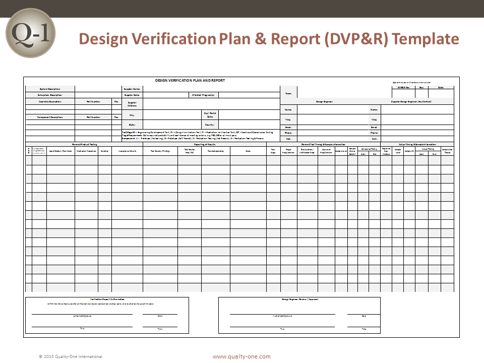
Read Quality-One’s overview of the Design Verification Plan and Report. Use it to understand how the verification relationships in your RTM become an executable test and analysis plan with later reported results.
Start with “What is Design Verification Plan and Report (DVP&R).” Read the DVP&R purpose, paying attention to the distinction between a requirement and the method used to verify it. Then read “The Body,” especially “The Planned Product Testing Section,” from the planned-test fields. Focus on method, duration, and acceptance criteria. Continue through “The Reporting of Results Section” and “The Planned Test Timing and Sample Section.” Read the result-recording fields, then note how test stage, sample level, sample quantity, location, responsibility, and timing establish whether evidence is appropriate for the decision being made.
A sensible relationship between the two records is:
| RTM purpose | DVP&R purpose |
|---|---|
| Maintains requirement, source, design, verification, evidence, and change relationships | Plans and records the execution of specific tests and analyses |
| Answers “Which requirement does this activity support?” | Answers “How, when, where, and on what samples will we run it?” |
| Supports completeness and change-impact review | Supports test readiness, execution, results, and reporting |
| Uses stable requirement and verification IDs | Reuses those IDs in detailed test-plan rows and reports |
Quality-One notes that DVP&R activity is closely associated with DFMEA, but the two have different functions. A DFMEA identifies how a design may fail and identifies prevention or detection actions. The DVP&R defines how relevant performance and verification claims will be assessed. Later in the course, you will link failure modes and special characteristics to requirements, DVP&R entries, and preliminary control plans. Do not make the DVP&R a copy of the DFMEA; link the records by ID and rationale.
Make the RTM reviewable at every design gate
A traceability matrix is useful only when it changes decisions. At each review, conduct a short coverage and readiness review rather than treating the sheet as an administrative deliverable.
Coverage checks
For every active approved requirement, confirm:
- it has at least one planned verification activity;
- the verification method is technically credible;
- the acceptance criterion is explicit;
- the activity has an owner and planned timing;
- the requirement links to its source and, where mature enough, to a design implementation;
- critical requirements have no unresolved
[TBD]value or unapproved source; - duplicated requirements have been consolidated or intentionally related.
Two simple indicators can expose gaps:
Use the percentages carefully. One missing environmental, safety, regulatory, or functional requirement may matter more than ten completed low-risk documentation checks. Review status by criticality as well as total count.
Readiness checks before a test or demonstration
Before authorizing a verification activity, confirm that:
- the correct requirement revision is referenced;
- acceptance criteria are approved;
- the sample configuration is identified;
- the test method and equipment are suitable;
- required fixtures, instruments, and calibration are available;
- the environmental and mounting conditions are specified;
- the responsible engineer and approver are assigned;
- expected evidence and report format are known.
Closure checks after execution
A requirement should not be marked Pass simply because a test was conducted. Its closure record should show:
- actual results compared with every stated acceptance criterion;
- sample and configuration identification;
- procedure and any deviations;
- anomalies or failures;
- corrective action or nonconformance reference where required;
- reviewer approval;
- a durable link to the signed report and supporting data.
NASA’s guidance is particularly firm on this point: a controlled closure artifact is objective evidence. An unsigned drawing, unsupported screenshot, or unapproved procedure may help engineering discussion, but it is not necessarily sufficient evidence to close a requirement.
If an activity fails, retain the original result. Set the RTM status to Fail / open nonconformance and link the issue record. The eventual retest, deviation, or corrective action becomes an additional controlled record. Never replace an inconvenient result with a new “Pass” row and erase the history.
A practical controlled workflow for this course
Create a workbook or controlled template called:
EDV_Program_Requirements_and_Verification_Register
Use at least three connected tabs:
-
Requirements Register
The approved atomic requirements from the previous lesson. -
RTM / Verification Plan
One row per requirement–verification pairing, using the fields defined in this lesson. -
Evidence Index
A controlled list of reports, analysis files, test photos, test procedures, inspection records, deviation records, and their revision or release status.
Use stable identifiers, for example:
- Requirement:
ECU-ENV-001 - Verification activity:
VFY-ECU-ENV-001-T01 - Test procedure:
TP-ECU-ING-001 - Evidence report:
TR-ECU-ING-001 - Assumption:
ASM-ECU-014 - Issue or nonconformance:
NCR-ECU-003 - Engineering change:
ECO-ECU-002
Do not encode the revision in the identifier. Instead, record revision in its own field. A stable ID lets you see that ECU-ENV-001 changed from one approved wording or verification plan to another, rather than losing traceability through a completely new name.
For an initial ECU-housing baseline, populate at least these requirement groups:
- enclosure retention and component protection;
- package envelope and vehicle mount interfaces;
- connector and service access;
- ingress and environmental exposure;
- material and electrical-isolation needs;
- manufacturability, tooling direction, and draft;
- mass and key physical allocations;
- marking, appearance, or identification where applicable.
At this point, incomplete information is expected. A properly controlled RTM makes the gaps visible:
| Status | Meaning |
|---|---|
| Draft | Statement or verification approach is being developed |
| Under review | Awaiting technical, quality, customer, or program approval |
| Approved / baselined | Requirement and planned verification are controlled inputs |
| Planned | Verification activity is approved but not yet executed |
| In progress | Activity has started; final evidence is not yet approved |
| Pass | Approved objective evidence demonstrates every criterion |
| Fail / open NCR | Evidence does not meet criterion; disposition is required |
| Waived / deviated | Formal authorized disposition exists; this is not the same as pass |
| Superseded | Replaced by a controlled revision; prior evidence retained for history |
This workflow is intentionally tool-independent. In the next PLM-focused lessons, the register, verification activities, CAD revisions, released drawings, EBOM and MBOM views, and ECO records will become linked managed objects. Until then, disciplined IDs, revision fields, baselines, and evidence links give you a credible approximation of that environment.
Common RTM failure modes
A few habits undermine traceability quickly:
| Failure mode | Why it is dangerous | Better practice |
|---|---|---|
| “Test” as the entire verification plan | Does not specify conditions, samples, or pass criteria | Reference an approved procedure and state measurable acceptance criteria |
| One broad row for several obligations | A single pass/fail result cannot prove several independent requirements | Split atomic requirements and create linked activities where needed |
| Using the same text for requirement and acceptance criterion | Often hides the actual measurement and threshold | State how compliance will be observed or measured |
| Linking to a generic standard title only | Applicability and test conditions remain ambiguous | Cite the document revision, relevant clause, and applicability rationale |
| Closing a requirement with early CAD evidence only | May ignore physical variation, assembly effects, and production configuration | Label it development evidence; retain physical or production-intent closure where needed |
| Losing the tested configuration | Makes results unusable after an ECO or material change | Record CAD, drawing, material, sample, and assembly revisions |
| Editing past results after a failure | Destroys the audit trail and hides risk | Preserve failure, link nonconformance and corrective action, then add the rerun evidence |
| Treating an assumption as a requirement | Gives unapproved information false authority | Link the assumption, confidence, owner, and closure date visibly |
A requirements traceability matrix turns a list of “shall” statements into a controlled verification strategy. Each active requirement needs a clear source, a credible verification method, explicit acceptance criteria, an owner, and eventually objective evidence tied to the exact product configuration.
For the ECU, door-trim, and HVAC projects, maintain a stable chain from requirement source through design implementation and verification activity to controlled evidence. Treat early analyses as development evidence unless they truly satisfy the agreed closure method; preserve failed results and change history rather than overwriting them; and never let an unapproved assumption masquerade as a released requirement.
Next, you will build a controlled standards register. That register will distinguish standards, regulations, customer-specific requirements, and automotive core tools by issuing body, applicability, revision, purpose, and required compliance evidence—giving the RTM reliable sources to trace against.
Can't find a good explanation? Sign up and we'll make it for you
Sign up