
Hello! Welcome to the fourth lesson in our module on Applied Power Systems.
In our last session, we established a method for sizing a generator by comparing the total real power (kW) and apparent power (kVA) of the loads against the generator's ratings. We concluded by noting that the large inrush current drawn by motors during startup is a critical, and often dominant, factor in this calculation.
Today, we will delve into the physics behind this phenomenon. The learning outcome for this lesson is to: Explain the physical origin of large starting currents in inductive loads (e.g., motors), referencing the initial absence of back-EMF. Understanding this will connect the abstract principles of electromagnetism to the practical challenges of power system design.
The Dual Nature of a Motor: Pushing and Pushing Back
The key to understanding a motor's behavior lies in recognizing that it is simultaneously a motor and a generator. Two fundamental principles of electromagnetism are at play:
- The Motor Effect: A current-carrying conductor placed in a magnetic field experiences a force (the Lorentz force). This force creates a torque that causes the motor's shaft to rotate. This is how electrical energy is converted into mechanical work.
- The Generator Effect (Faraday's Law of Induction): A conductor moving through a magnetic field experiences a changing magnetic flux. This change induces an electromotive force (EMF), or voltage, across the conductor.
When you power a motor, the motor effect causes its internal coils (the armature) to rotate. As these coils rotate through the motor's internal magnetic field, they are, by definition, conductors moving through a magnetic field. This induces a second EMF due to the generator effect.
According to Lenz's Law, this induced EMF must oppose the change that created it. The "change" is the rotation driven by the original supply voltage. Therefore, this self-generated EMF acts in the opposite direction to the supply voltage. We call this the back electromotive force, or back-EMF ().

How Back-EMF Regulates Current
The back-EMF acts as a self-regulating brake on the current flowing into the motor. Since it directly opposes the supply voltage, the net voltage across the armature's resistance is the difference between the two:
Given your background in econometrics and differential equations, you can think of this as a dynamic system reaching equilibrium. The current flowing through the armature, which has a resistance , is determined by this net voltage, according to Ohm's Law:
This equation is the key to understanding the entire process. The back-EMF, , is not constant; it is directly proportional to the rotational speed () of the motor. The faster the motor spins, the greater the rate of change of magnetic flux, and the larger the back-EMF it generates.
The Startup Condition: The Origin of Inrush Current
Now, let's analyze the exact moment the motor is switched on.
- At time , the motor is stationary. Its rotational speed is .
- Since back-EMF is proportional to speed, at this moment, .
Substituting this into our governing equation gives the starting current:
Motor armatures are built with conductors that have a very low resistance, , to minimize power loss () and maximize efficiency during normal operation. A small denominator () and a full supply voltage in the numerator result in a very large starting current. This massive initial current is the inrush current or surge load we discussed in the previous lesson.
The Running Condition: Reaching Equilibrium
As this large current flows, it produces a strong torque, and the motor begins to accelerate. As its speed increases:
- The back-EMF, , increases.
- The net voltage, , decreases.
- The armature current, , decreases accordingly.
The motor's speed will increase until it reaches an equilibrium where the torque produced by the current is just enough to overcome the mechanical load on the shaft and internal friction. At this point, the current settles to its much lower, stable running current.
The following video provides an excellent walkthrough of this entire process, including a clear numerical example.
What is Back EMF & what is its significance | DC Motor | TheElectricalGuy
To see this effect quantified, the video 'What is Back EMF & what is its significance' by TheElectricalGuy provides a clear walkthrough.
Watch the segment from 03:56 to 08:59. This part first explains how the rotating armature generates the opposing back-EMF. Then, crucially, it steps through a calculation showing how the current is extremely high at startup (when back-EMF is zero) and then drops significantly as the motor speeds up and back-EMF builds. Pay close attention to the formula I = (V_supply - V_back_emf) / R_armature.
Now, let's solidify this concept with a practical calculation.
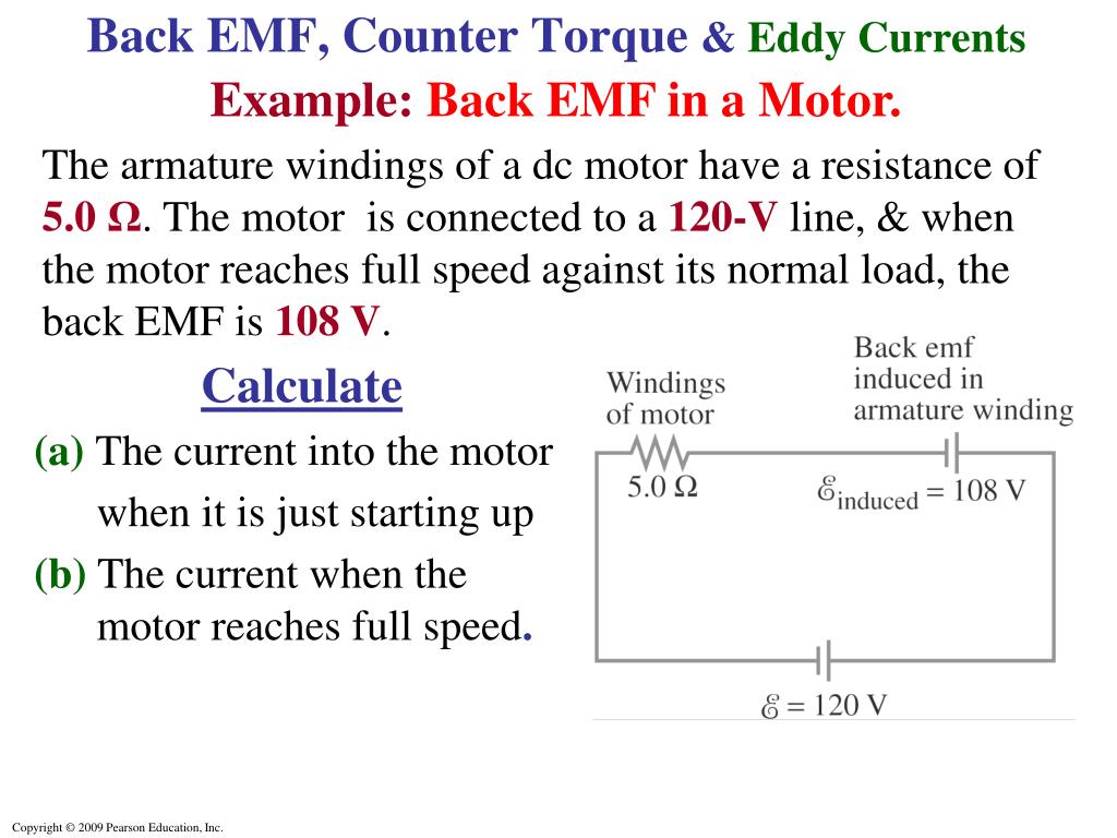
Test your understanding!
Using the values from the image above:
- A DC motor has an armature winding resistance of .
- It is connected to a source.
- At full speed, the back-EMF is .
Calculate:
a) The starting current (when the motor is just turned on).
b) The current when the motor is running at full speed.
Show answer
The governing equation is .
a) Starting Current:
At startup, the motor isn't rotating, so the back-EMF .
b) Full-Speed Current:
At full speed, the back-EMF is given as .
Notice the starting current (48 A) is 8 times the running current (6 A). This huge initial surge is the inrush current that a power source like a generator must be able to handle momentarily.
This explains a common real-world observation: when a heavy appliance with a motor (like a refrigerator or air conditioner) starts, the lights in the house may briefly dim. The large inrush current causes a temporary voltage drop () in the home's wiring, which is noticeable in other connected devices.
Conclusion
You can now explain precisely why motors draw such a large current when they start. It is not an arbitrary property but a direct consequence of the laws of electromagnetism.
Key Takeaways:
- A running motor acts as both a motor and a generator, producing a back-EMF that opposes the supply voltage.
- The back-EMF is proportional to the motor's rotational speed.
- The current drawn by the motor is determined by the net voltage () across the armature's resistance.
- At startup, speed and back-EMF are zero. The full supply voltage is applied across the very low armature resistance, resulting in a large inrush current.
- As the motor speeds up, back-EMF increases, which reduces the net voltage and brings the current down to its normal operating level. This is a natural self-regulation mechanism.
Preview of the Next Lesson:
We have now demystified the surge load. In our next lesson, we will apply this physical understanding to the practical task of generator sizing. The learning outcome will be to: Incorporate surge load considerations when sizing a generator for a specific set of appliances. We'll look at how manufacturers specify a generator's surge capacity and how to ensure your chosen generator can successfully start your largest motor.
Can't find a good explanation? Sign up and we'll make it for you
Sign up