
Creating Consistent System Design Documentation
Welcome to the final lesson of your course on UML and Mermaid. Over the past eight lessons, you have built a solid foundation in creating various diagrams to model different aspects of a system. Now, we will bring all those pieces together.
This lesson addresses the capstone learning outcome: assembling a concise and consistent design document. We will focus on how to combine architecture, data, and interaction diagrams into a single Markdown document to present a coherent, multi-faceted view of a system. You will learn not just how to place these diagrams together, but more importantly, how to cross-check them to ensure they tell a consistent story. This is the skill that transforms individual diagrams from simple illustrations into a powerful engineering tool.
The "Docs-as-Code" Philosophy
As a developer with extensive experience, you are intimately familiar with the power of version control systems like Git for managing source code. The same principles that make Git indispensable for code—traceability, collaboration, and maintainability—can and should be applied to documentation. This is the core idea behind "documentation-as-code."
By defining diagrams in a text-based format like Mermaid and embedding them in Markdown files, you colocate your design documentation with the code it describes. This approach has several advantages:
- Version Control: Design changes can be tracked, reviewed, and reverted just like code changes.
- Consistency: When a developer pulls the latest version of the code, they also get the latest version of the documentation.
- Maintainability: Updating a diagram is as simple as editing a few lines of text, eliminating the need for specialized graphical editing tools and the hassle of re-exporting and re-uploading static images.
To explore this philosophy further, start by reading the following article. It eloquently explains why making diagramming as seamless as writing Markdown is a superpower for developers.
Mastering Mermaid JS: The Visual Superpower Every ...
This article from the GitConnected blog discusses the benefits of text-based diagramming.
Please read the introduction and the section Why Use Mermaid JS?. Focus on how the author connects plain-text syntax to benefits like version control, developer-centric tooling, and easier maintenance in agile environments.
Structuring a Design Document: The Arc42 Template
Just as you wouldn't start a complex software project without some architectural plan, a good design document benefits from a clear and logical structure. A widely respected standard for structuring software architecture documentation is the arc42 template. It provides a practical, question-based framework to ensure all critical aspects of a design are covered.
While the full template is comprehensive, we can use a simplified version to organize our multi-view document.
Documenting Software Architecture in Code Repository
This article explains how to use templates like arc42 to structure architectural documentation within a code repository.
Please read the section titled Arc 42 Template. Pay attention to the list of 12 sections. We will focus on a few key ones: Section 5: Building Block View: This is where our architectural diagrams (like component or flowchart diagrams) will go. Section 6: Runtime View: This is the perfect place for our interaction diagrams (like sequence diagrams). Data Models: While not explicitly a top-level section, Entity-Relationship Diagrams (ERDs) are a crucial part of the design and are often linked from the building block or runtime views.
Building a Coherent Multi-View Model
Now, let's apply these ideas to a concrete example: a simple online bookstore. We will create three distinct but related views of this system: an architectural view, an interaction view, and a data view.
View 1: The Architecture (Building Block View)
First, we need a high-level overview of the system's main components and how they fit together. A flowchart with subgraphs is an effective way to represent logical layers or services in Mermaid. This gives us a "building block" or component-style view.
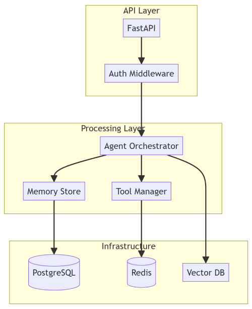
Here is the Mermaid code for our bookstore's architecture. It defines three layers: a public-facing Frontend, a Backend for business logic, and a Persistence layer.
This diagram establishes the main actors and components: User, Frontend, Backend, Database, and PaymentGateway.
View 2: An Interaction Scenario (Runtime View)
Next, let's zoom in on a specific runtime scenario: a user purchasing a book. A sequence diagram is the ideal tool for this, as it shows the ordered flow of messages between the participants we just defined.

Here is the Mermaid code for our "Buy Now" scenario. Notice that the participants—User, Frontend, Backend, PaymentGateway, Database—are the same components we identified in our architecture diagram.
View 3: The Data Model
Finally, several interactions in our sequence diagram involve the Database. The "Create Order" step implies a certain data structure. An Entity-Relationship Diagram (ERD) allows us to model this structure explicitly.
Here is the Mermaid code for a simplified ERD for our bookstore.
The Critical Step: Cross-Checking for Consistency
Having three separate diagrams is useful, but their real power comes from being mutually consistent. An inconsistent set of diagrams is worse than no diagrams at all, as it creates confusion. Let's practice cross-checking our three views.
-
Architecture ↔ Sequence:
- Question: Are all the participants in the sequence diagram (
User,Frontend,Backend,Database,PaymentGateway) represented in the architecture diagram? - Check: Yes, they are.
- Question: Do the interactions in the sequence diagram respect the connections in the architecture diagram? (e.g., the
Frontendonly talks to theBackend, not directly to theDatabase). - Check: Yes. The flow is
Frontend→Backend→Database, which matches the architectural layers.
- Question: Are all the participants in the sequence diagram (
-
Sequence ↔ ERD:
- Question: When the
Backendreceives a "Create Order" request, what data does it need? The sequence diagram shows it interacts with theDatabase. Does the ERD support this? - Check: Yes. The ERD has an
ORDERStable (withuser_id,total_price) and anORDER_ITEMStable (withorder_id,book_id). TheBackendcan create rows in these tables to fulfill the request. The entities and relationships exist as required by the interaction.
- Question: When the
-
Architecture ↔ ERD:
- Question: Which component is responsible for managing the data defined in the ERD?
- Check: The architecture diagram shows the
Backendcomponent is the one that communicates with theDatabase. This implies theBackendcontains the data access logic for the entities defined in the ERD. ThePersistence Layerlogically "contains" the schema shown in the ERD.
This cross-checking process ensures that your design is coherent and that each diagram reinforces the others, providing a deep and accurate understanding of the system from multiple perspectives.
To see more examples of these different diagram types used together for a single system, you can review the "Diagram Types" section in the "Mastering Mermaid JS" article you read earlier.
Mastering Mermaid JS: The Visual Superpower Every ...
This section provides code for five different diagram types all related to the same bookstore theme.
Review the examples for Flowcharts through ERDs. Notice how they each model a different aspect—process, interaction, structure, state, and data—of the same conceptual system.
Your Turn: Assemble the Design Document
Now it is your turn to act as the architect. Your task is to create a single Markdown file named bookstore_design.md.
- Create the File: Use an editor that supports Mermaid rendering, like VS Code with a Mermaid plugin, or an online platform like GitHub or GitLab.
- Structure the Document: Use a simplified
arc42structure with Markdown headings:# 1. Introduction and Goals# 5. Building Block View# 6. Runtime View# Data Model
- Embed the Diagrams: Copy the three Mermaid code blocks provided in this lesson (the architecture flowchart, the "Buy Now" sequence diagram, and the ERD) and place them under the appropriate headings in your Markdown file.
- Add Narrative: Under each heading, write one or two sentences of your own explaining what the diagram shows and how it relates to the others. For example, under "Runtime View," you might write: "This sequence diagram illustrates the 'Buy Now' process, showing how the components defined in the architecture view collaborate to process an order."
This exercise will solidify your understanding of how to weave multiple diagrams into a single, coherent narrative that effectively documents a software system.
Conclusion
Congratulations on completing the course! In this final lesson, you've learned to bring together everything you've practiced. The key takeaways are:
- Documentation-as-Code: Treating diagrams as text within your version-controlled repository makes them easier to maintain, review, and keep in sync with your project.
- Multi-View Modeling: Complex systems cannot be understood from a single perspective. Combining architectural, interaction, and data diagrams provides a holistic view.
- Structure is Key: Using a template like
arc42helps organize your design document, ensuring you cover the most critical aspects. - Consistency is Crucial: The most important skill is cross-checking your diagrams to ensure they are mutually consistent and tell a single, coherent story about your system.
By mastering these skills, you've moved beyond simply knowing Mermaid syntax. you are now equipped to create clear, maintainable, and powerful design documentation—a truly valuable capability for any lead developer.
Can't find a good explanation? Sign up and we'll make it for you
Sign up