
Hello. In the previous lesson, you established the project container: Documents, Part Studios, assemblies, versions, releases, and the distinction between an EBOM and an MBOM. This lesson narrows from where CAD information lives to how authoritative geometry travels through the model without creating brittle links.
For an automotive plastic assembly, robust parametric design is not simply making dimensions editable. It means that a change to an approved mounting location, connector datum, package envelope, or sealing plane reaches every affected component predictably, while unrelated geometry remains isolated. The mechanism is a master skeleton plus a disciplined set of published references.
By the end, you will be able to define what belongs in an ECU-housing skeleton, construct a practical Onshape reference package using Derived geometry and mate connectors, decide when to use workspace versus version references, and map the same intent to CATIA V5/V6 publications and ENOVIA-controlled interfaces.
1. The master skeleton is an interface model, not an early CAD model
A master skeleton is a deliberately lightweight parametric model that owns the geometry needed to position, size, and connect a subsystem. It does not attempt to represent the finished base, cover, gasket, PCB, and vehicle bracket in simplified form.
For the assumption-based high-voltage ECU enclosure, the skeleton should answer questions such as:
- Where is the vehicle installation coordinate system?
- Where are the four mounting axes and their seating planes?
- What is the permitted package envelope?
- What space must remain clear for the connector, harness bend, vent, and service tool?
- Where is the PCB datum and maximum PCB volume?
- Where is the nominal sealing interface?
- Which team owns each interface and what baseline defines it?
It should not contain production ribs, bosses, cosmetic fillets, draft faces, or detailed threaded inserts. Those belong to their owning components.
Think of the skeleton as the controlled interface-control model expressed in CAD. It holds the few facts that must remain consistent across several parts.
| CAD content | Belongs in skeleton? | Why |
|---|---|---|
| Vehicle installation coordinate system | Yes | Every installed component needs a common orientation and datum. |
| Mounting-point axes and seating faces | Yes | The base, bracket, fasteners, and vehicle-side check all depend on them. |
| ECU maximum package envelope | Yes | It controls packaging without prescribing detailed part geometry. |
| Connector datum, approach direction, and keep-out | Yes | It is a shared electrical, harness, service, and packaging interface. |
| PCB datum, envelope, and support-zone limits | Yes | It aligns housing features to an electronics interface without embedding PCB detail. |
| Sealing-plane reference and perimeter-control sketch | Yes | The base, cover, gasket, and compression-stop strategy depend on it. |
| Housing-base ribs, bosses, and gussets | No | These are manufacturing and structural details owned by the base part. |
| Cover cosmetic texture boundaries | No | These belong to the cover design and appearance definition. |
| Supplier connector CAD | Usually no | Use a simplified supplier-controlled envelope and defined connection datums instead. |
The important distinction is between a reference and a representation. A simplified connector envelope is a reference: it claims only the clearance and interface space that downstream designers require. A fully detailed supplier connector is a representation: it adds geometry, performance cost, and revision-management burden that the skeleton usually does not need.
2. Publish interfaces, not incidental geometry
A published reference is a named piece of geometry or information intentionally made available to downstream users. In CATIA, this is literally called a Publication. In Onshape, the same behavior is created through carefully named sketches, planes, axes, mate connectors, surfaces, and Derived features.
The word intentional matters. If a cover model happens to reference the outer edge of a base-part fillet, it may work today, but it is not an interface contract. That edge can move, split, disappear, or change identity when the base designer modifies draft, wall thickness, or radii.
A published reference should instead expose a stable functional datum: a plane, point, axis, coordinate system, curve, or controlled surface.
Read “About Publications” to establish the central CATIA and 3DEXPERIENCE idea: a publication is an intentional layer between an internal design feature and the people or components permitted to reference it.
On the “About Publications” page, begin with the opening definition. Focus on the phrase “separate the design from the pointed object.” Then continue through the Object Selection discussion, noting that points, lines, curves, planes, sketches, bodies, and features can be published. The key question is not “what can be published?” but “what must another component be allowed to rely on?”
For the ECU assembly, a compact reference package might look like this:
| Published-reference ID | Geometry type | Functional meaning | Typical consumers |
|---|---|---|---|
MC_EDV_INSTALL_CS | Mate connector / coordinate system | Installed vehicle orientation and master origin | Base, cover, assembly, validation fixtures |
MC_MOUNT_FL through MC_MOUNT_RR | Mate connectors | Mount-hole center, axis, and local orientation | Base, vehicle bracket, fasteners, FEA setup |
PLN_MOUNT_SEAT | Plane | Nominal vehicle-side mounting seating condition | Base mounting pads, stack analysis |
ENV_ECU_MAX | Surface or simplified solid | Maximum allocated package volume | Base, cover, adjacent-system clearance check |
MC_CONN_A_DATUM | Mate connector | Connector location and clocking | Base opening, connector supplier geometry, harness study |
ENV_CONN_A_KEEPOUT | Surface / simplified solid | No-intrusion volume for connector and harness | Base, cover, service-access study |
SK_PCB_DATUM | Sketch or plane | PCB placement, support zones, and locating origin | Base PCB supports, cover clearance check |
SK_SEAL_PERIMETER | Closed sketch | Nominal gasket and sealing-land path | Base, cover, gasket-interface model |
PLN_COVER_MATE | Plane | Primary base-to-cover relationship | Base, cover, gasket compression analysis |
This set is small enough to understand in a review, yet complete enough to protect the critical interfaces.
A publication is a contract
A useful rule is:
A downstream part may depend on an upstream feature only when the upstream owner is prepared to control that feature as an interface.
For example, the base and cover may both use SK_SEAL_PERIMETER, but neither should take a dependency on the other part’s drafted outer wall. The first is a declared shared functional requirement. The second is an implementation choice.
This gives the model a clear direction of authority:
- The skeleton owns shared package and functional interfaces.
- The base, cover, gasket, and bracket consume only the interfaces they need.
- The assembly evaluates fit and access using those controlled component definitions.
- Drawings and verification evidence identify the same functional datums where appropriate.
3. A dependency structure that can survive engineering changes
The safest default for your ECU project is a single-hub architecture. The master layout feeds each component directly. Components do not feed one another.
| Source | Downstream object | Allowed dependency |
|---|---|---|
PS_00_Master_Layout | PS_10_Housing_Base | Mounting connectors, PCB references, package envelope, sealing perimeter |
PS_00_Master_Layout | PS_20_Housing_Cover | Package envelope, connector keep-out, sealing perimeter, cover-mating plane |
PS_00_Master_Layout | PS_30_Gasket_Interface | Sealing perimeter, gasket cross-section reference, compression direction |
PS_00_Master_Layout | PS_40_PCB_Supports | PCB origin, PCB envelope, base mounting interfaces |
| Component Part Studios | ASM_1000_ECU_Envelope | Released or review-level part definitions only |
Avoid these dependency patterns:
- Base Part Studio derives the cover, then the cover derives a revised base.
- Cover references a rib edge on the base.
- Gasket groove geometry is copied manually into both base and cover.
- A detailed component derives from another component that itself was only derived from the master layout.
- A part in a downstream document is used to redefine the upstream skeleton.
The last case is a circular dependency. Onshape prohibits circular Derived references, but you should avoid even a logically circular decision loop: for example, the master layout should not be altered merely to preserve a non-functional rib location in the base.
Derived - https : / / cad . onshape . com
Read the Onshape Help page “Derived” for the formal behavior of the Derived feature. It establishes why Derived geometry is suitable for a master-model workflow, but also why reference direction and version control must be managed deliberately.
In the opening overview, read the one way association. Notice that change propagates from the source to the derived instance, not back to the source. Then find the later best-practice guidance beginning with version references. Focus on the recommendation to use versions when practical, derive lightweight source geometry, and avoid long chains of Derived instances.
The official guidance to avoid chains is particularly important. A hierarchy of master model, subsystem model, and detailed components can be valid in a very large vehicle program, but each extra level makes the dependency graph harder to inspect and update. For this ECU project, use the simpler structure: one master skeleton and direct, selective Derived references into each detailed component.
If a later project genuinely needs a subsystem skeleton, keep it lightweight and document why it exists. Do not create an informal chain simply because a convenient piece of geometry already exists in another Part Studio.
4. The Onshape implementation: master layout, mate connectors, and Derived references
The master-skeleton strategy can be executed in the Onshape document structure created in the previous lesson.
Step 1: Build a sparse master layout
In PS_00_Master_Layout, create reference geometry before creating parts.
A practical feature-list order is:
MC_EDV_INSTALL_CSSK_PACKAGE_ENVELOPEENV_ECU_MAXMC_MOUNT_FL,MC_MOUNT_FR,MC_MOUNT_RL,MC_MOUNT_RRPLN_MOUNT_SEATMC_CONN_A_DATUMENV_CONN_A_KEEPOUTSK_PCB_DATUMPLN_COVER_MATESK_SEAL_PERIMETER
A mate connector is especially effective because it carries a point, three oriented axes, and a plane-like local coordinate system in one object. It is therefore stronger than a point alone when a fastener, connector, or assembly fixture needs a defined orientation.
Top down design of complex assemblies with Onshape
Watch Greg Brown’s “Top down design of complex assemblies with Onshape” for a practical explanation of mate connectors as compact coordinate-system references and for a demonstration of the published-geometry idea in Onshape.
Watch mate connectors first. Focus on why a mate connector can replace several separate construction entities. Then watch published geometry. Observe the workflow of collecting only needed reference geometry and deriving it into another Part Studio; do not treat a composite or derived package as permission to pass complete detailed parts everywhere.
For a vehicle-mounted ECU, orient MC_EDV_INSTALL_CS according to a declared vehicle convention. For example, your assumptions register may define:
- : vehicle forward
- : vehicle left
- : vehicle upward
The convention itself is not universal; consistency and documentation are the requirements. Place all mounting and connector mate connectors relative to that master coordinate system, not relative to temporary construction faces.
Step 2: Create a clear reference package
You have two reasonable Onshape approaches:
| Approach | Use when | Recommended content |
|---|---|---|
| Derive individual sketches, planes, and mate connectors | The component needs a few specific references | Sealing sketch, PCB plane, mounting mate connectors |
| Create a compact reference package | Several related references form one interface zone | Connector datum, keep-out surfaces, mounting references, common coordinate system |
A package should be organized by functional zone rather than by arbitrary CAD type. For instance, REF_Connector_A may include one mate connector, a keep-out volume, a mounting plane, and an opening-boundary sketch because together they define one connector interface.
Keep the geometry as light as possible. A base model does not need the detailed CAD of an electronic connector merely to position an opening and preserve harness clearance. It needs the connector’s installation datum, a bounding envelope, perhaps an approved opening boundary, and a documented revision.
Step 3: Derive references as the first feature in each component Part Studio
In PS_10_Housing_Base, make the Derived feature the first meaningful feature. Derive only:
MC_EDV_INSTALL_CS- The four mounting mate connectors
PLN_MOUNT_SEATENV_ECU_MAXMC_CONN_A_DATUMENV_CONN_A_KEEPOUTSK_PCB_DATUMSK_SEAL_PERIMETER
In PS_20_Housing_Cover, derive only what the cover owns:
MC_EDV_INSTALL_CSENV_ECU_MAXMC_CONN_A_DATUMENV_CONN_A_KEEPOUTPLN_COVER_MATESK_SEAL_PERIMETER
This difference is significant. The cover does not need a copied set of base-only mounting features merely because they exist in the skeleton.
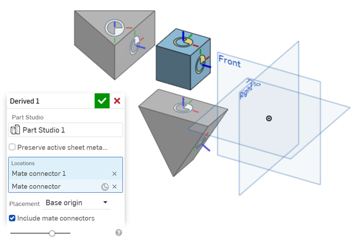
When positioning derived geometry, use the defined master origin or explicit mate connectors rather than manually translating it. The following image shows the Derived dialog’s use of a location mate connector, base-origin versus base-mate-connector placement, and the option to include mate connectors in the derived result.
Step 4: Consume references without turning them into geometry ownership
Derived references should drive features through intentional constraints:
- Constrain mounting-hole centers to the derived mounting mate connectors.
- Build the connector opening from the derived connector datum and opening boundary.
- Locate PCB supports from the derived PCB plane and datum sketch.
- Build the groove path and sealing land from the derived sealing-perimeter sketch.
- Check that the outer housing remains within the derived maximum envelope.
Do not edit derived geometry in the target Part Studio. If an interface needs to change, raise an issue against its owning skeleton reference. A cover designer may propose that the connector move for tooling access, but the approved connector datum must be changed by the interface owner through the appropriate review and change record.
Tech Tip: Creating Master Sketches with Onshape’s Derived Feature
Watch Onshape’s short “Tech Tip: Creating Master Sketches with Onshape’s Derived Feature.” It provides a compact workflow for keeping a governing sketch and construction geometry in one Part Studio while allowing detailed parts to remain separate.
Watch the complete workflow. Note the sequence: keep the master Part Studio limited to governing sketches and reference geometry, create separate component Part Studios, then derive the relevant master sketch into each component. The same approach applies to mate connectors, planes, and lightweight envelopes in your ECU skeleton.
5. Design updates: automatic propagation is not the same as controlled change
A robust skeleton causes downstream features to update. A controlled automotive process decides when that update is accepted.
In active concept work within one Onshape document, a workspace reference may be reasonable when one engineer or a tightly coordinated team is iterating rapidly. Changes in the master layout then update the dependent Part Studios immediately.
Before a formal design review, supplier package issue, or drawing release, change the relationship from an uncontrolled moving reference to a known baseline wherever practical.
| Development state | Skeleton reference choice | Why |
|---|---|---|
| Early concept exploration | Workspace reference can be appropriate | It supports rapid integration while requirements are still fluid. |
| Preliminary design review | Named version of the skeleton | Reviewers see a stable package and know exactly what was assessed. |
| Supplier quotation or tooling-feasibility package | Named version with controlled reference register | The supplier should not receive a moving interface definition. |
| Released engineering definition | Released or approved controlled revision | Changes require documented impact assessment and approval. |
| Post-release correction | New skeleton revision linked to an ECO | The change remains traceable to affected CAD, drawings, BOMs, and validation. |
For example, suppose a package review changes the assumed connector approach by in the vehicle direction. The right process is not simply to move the connector opening in the base.
Instead:
- Record the proposed change in the assumptions log or ECO intake.
- Assess which skeleton references change: likely
MC_CONN_A_DATUMandENV_CONN_A_KEEPOUT. - Update the skeleton in a controlled workspace.
- Review the regenerated base, cover, gasket-interface, harness-clearance, and service-access results.
- Resolve failures or geometry changes in the affected detailed models.
- Update relevant drawings, EBOM items, validation plans, risks, and supplier communication.
- Create a new version or release revision with the decision and impact evidence recorded.
This is why an update that propagates automatically is useful, but not sufficient. Regeneration proves geometric consistency; change control proves engineering authorization.
6. CATIA V5/V6 mapping: publications preserve the same contract
In CATIA V5, the master skeleton would commonly be organized in a master CATPart, often using clearly named Geometrical Sets for construction and interface geometry. Create planes, points, axes, sketches, parameters, and envelope surfaces there. Then use the Publication command to expose only the geometry that other parts are intended to consume.
A typical CATIA V5 publication set for the ECU could include:
PUB_EDV_INSTALL_CSPUB_MOUNT_FLPUB_MOUNT_FRPUB_MOUNT_RLPUB_MOUNT_RRPUB_CONN_A_DATUMPUB_CONN_A_KEEPOUTPUB_PCB_DATUMPUB_SEAL_PERIMETERPUB_COVER_MATE
Downstream CATPart models should create external links to those publications rather than directly selecting arbitrary upstream faces, edges, or features.
The critical benefit appears during a design change. If the skeleton designer replaces one construction plane with another but preserves the meaning and identity of PUB_PCB_DATUM, the downstream PCB-support model can remain linked to the publication contract rather than failing because its original supporting face no longer exists.
In a CATIA V6 or 3DEXPERIENCE environment, the same principle applies, but the publication and its associated representation can be managed within a product structure and governed with lifecycle controls. ENOVIA then provides the surrounding management layer: ownership, maturity state, effectivity where configured, baselines, change actions, approvals, and relationships between the engineering item and its CAD representation.
The terminology differs between systems, but the engineering intent is consistent:
| Engineering intent | Onshape implementation | CATIA V5 / V6 implementation | PLM control |
|---|---|---|---|
| Declare vehicle origin | Named mate connector | Published axis system / coordinate-system reference | Interface owner and baseline |
| Declare mount position and orientation | Mate connector | Published point, axis, or plane | Requirements and drawing linkage |
| Define a connector installation interface | Mate connector, sketch, and keep-out envelope | Publications of relevant datum geometry | Supplier revision and interface-control record |
| Transfer the interface to a component | Derived sketch, plane, surface, or mate connector | External reference to publication | CAD dependency traceability |
| Freeze what was reviewed | Onshape Version | Managed revision or baseline | Design-review record |
| Approve a changed interface | New version or release workflow | ENOVIA change and maturity workflow | ECO, approvals, and effectivity evidence |
7. Your ECU skeleton definition of done
Before advancing to molding direction, parting strategy, and draft analysis, your master-skeleton architecture should satisfy the following criteria.
CAD criteria
PS_00_Master_Layoutcontains only package, functional-interface, clearance, and locating geometry.- Every shared reference is named by function, not by creation order.
- Every component Part Studio begins with its required Derived references.
- No detailed component relies on an arbitrary external fillet edge, drafted face, or cosmetic surface.
- The base, cover, gasket interface, and PCB-support concepts receive their positions from the master layout.
- The complete assembly can be rebuilt after a controlled skeleton change without manually relocating components.
Interface and PLM criteria
- Each published reference has an owner and a stated purpose.
- Public information, engineering assumptions, controlled interfaces, and supplier-controlled interfaces remain visibly distinguished.
- A version name identifies the master-layout baseline used at design review.
- The baseline register records the version, scope, open assumptions, review decision, and resulting actions.
- A proposed interface change has a traceable route to the affected CAD, drawings, EBOM, validation evidence, and supplier communication.
A lightweight reference register
Add this register to your 00_Control material or project template:
| Reference ID | Description | Owner | Source status | Consumers | Baseline |
|---|---|---|---|---|---|
MC_EDV_INSTALL_CS | Assumed ECU installed coordinate system | Vehicle integration | Engineering assumption | Base, cover, assembly | V0.2_PDR |
MC_CONN_A_DATUM | Connector A installation location and clocking | Electrical integration | Controlled interface | Base, cover, harness study | V0.2_PDR |
ENV_CONN_A_KEEPOUT | Simplified harness and connector clearance volume | Electrical integration | Engineering assumption | Base, cover, service study | V0.2_PDR |
SK_SEAL_PERIMETER | Nominal gasket path | Enclosure design | Controlled interface | Base, cover, gasket | V0.2_PDR |
SK_PCB_DATUM | PCB origin and support-zone layout | Electronics integration | Supplier-controlled interface | Base, cover | Supplier model revision or assumption baseline |
This table is small, but it turns a hidden CAD dependency into a reviewable engineering interface.
Key takeaways
A master skeleton is a lightweight model that owns shared package, locating, clearance, and functional-interface geometry. Its job is to make changes predictable without forcing every component into one Part Studio.
- Publish stable functional references, not incidental faces and edges.
- In Onshape, use named sketches, planes, surfaces, and especially mate connectors; pass them to detailed Part Studios with the Derived feature.
- Prefer a single-hub dependency structure for the ECU project: master layout directly supplies the base, cover, gasket interface, and related models.
- Keep Derived geometry lightweight, avoid unnecessary derived-part chains, and prevent component-to-component dependencies.
- Use workspace references only deliberately during active iteration; use named versions or release-controlled references at reviews, supplier exchanges, and release points.
- In CATIA, use Publications as the formal interface-contract layer; in ENOVIA, govern those interfaces through maturity, baselines, and engineering changes.
- Treat every shared CAD reference as an owned engineering interface with a purpose, source status, consumers, and baseline.
Next, you will apply this architecture to plastic-part tooling intent by defining the ECU housing’s mold opening direction, parting strategy, shutoffs, and any required side actions.
Can't find a good explanation? Sign up and we'll make it for you
Sign up