
Welcome back. In the previous lesson, you learned to distinguish an Ethernet link that is merely up from one that is actually healthy, using negotiated parameters and counter patterns as evidence. That work matters here: every packet journey depends on each individual Layer 2 hop being able to carry intact frames.
This final lesson of the Ethernet foundations module puts the pieces together. You will trace one IP packet across switches and routers, identify exactly which headers remain stable and which are rebuilt, and learn how to verify that reasoning in captures from different points on the path. This is a core skill for troubleshooting routed firewall paths, transit networks, cloud attachments, and asymmetric flows.
Two delivery scopes in the same transmission
When an application sends data to a remote host, multiple layers describe the delivery at once:
| Layer | Unit commonly discussed | Delivery scope | Key identifiers |
|---|---|---|---|
| Transport | TCP segment or UDP datagram | End to end between processes | Source and destination ports |
| Network | IP packet | End to end between IP hosts | Source and destination IP addresses |
| Data link | Ethernet frame | One local Layer 2 segment | Source and destination MAC addresses |
The key distinction is:
IP addresses describe the end hosts; MAC addresses describe the next local delivery.
Suppose a client sends a TCP request to a server in another subnet. The client creates an IP packet whose destination is the server IP, not the default gateway IP. But it places the default gateway's MAC address in the destination field of the first Ethernet frame, because the gateway is the next device that must receive the frame.
An Ethernet frame is therefore a local wrapper around an IP packet. Its general shape is:
The EtherType field in the Ethernet header tells the receiver what is inside the frame. For IPv4, the EtherType is commonly 0x0800; for IPv6, 0x86DD. The FCS trailer provides a link-level integrity check for that particular transmission.
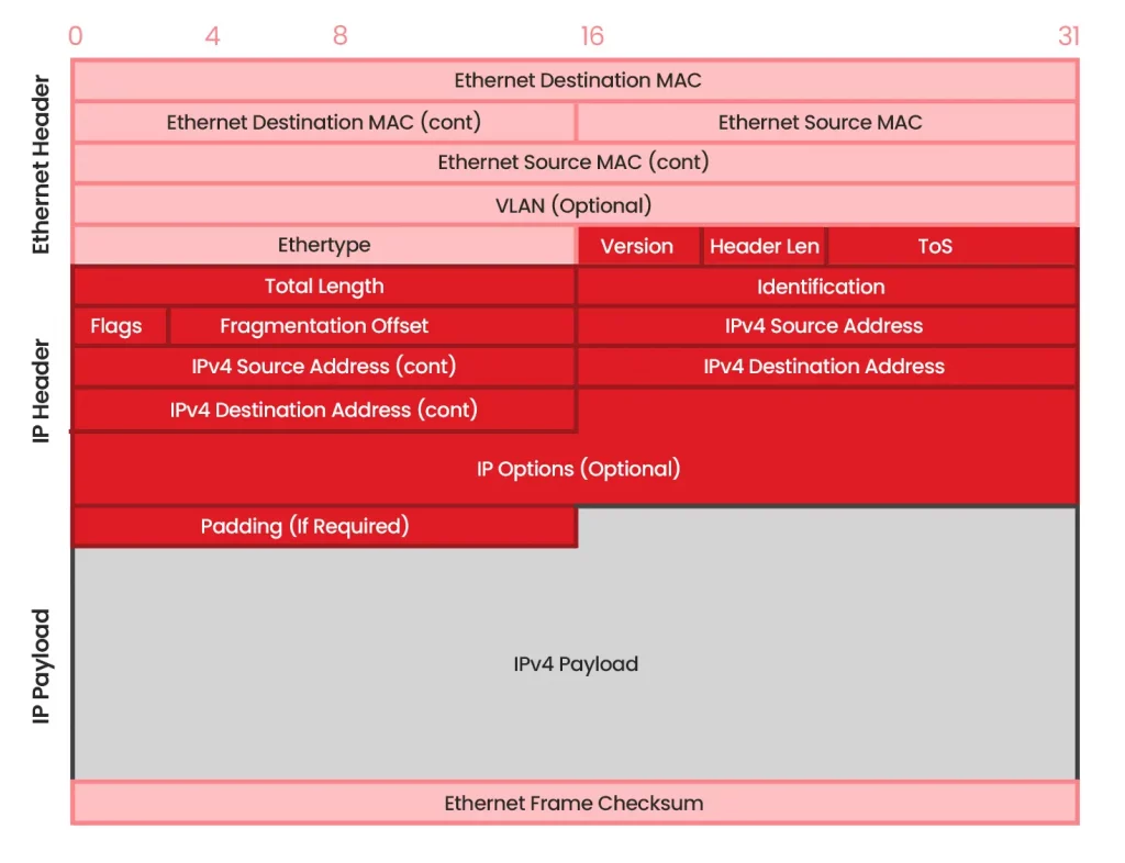
For ordinary routed forwarding, without NAT, tunneling, or a proxy in the path, the following is the practical rule:
| Field or component | Across a switch | Across a router |
|---|---|---|
| TCP/UDP ports and application payload | Preserved | Preserved |
| Source and destination IP addresses | Preserved | Preserved |
| IPv4 TTL | Preserved | Decremented by one |
| IPv4 header checksum | Preserved | Recalculated because TTL changed |
| IPv6 Hop Limit | Preserved | Decremented by one |
| Ethernet source and destination MAC | Preserved | Replaced for the outgoing link |
| Ethernet FCS | Validated and regenerated by Ethernet hardware as needed | Validated on ingress; a new outgoing frame has a new FCS |
| VLAN tag | Normally preserved through the same VLAN on a trunk | May be removed, added, or changed at a Layer 3 VLAN boundary |
“Preserved” here means that the device does not logically rewrite the field during normal forwarding. Ethernet hardware receives and retransmits bits on each physical segment, so captures may differ in low-level details such as FCS visibility. The meaningful Layer 2 addresses remain unchanged through a switched path, while a router creates a new Layer 2 delivery context.
A concrete path: client, switches, and two routers
Consider this path. Assume all ARP and switch MAC-table entries have already been learned, so the data packet can move immediately.
| Device or interface | IPv4 address | MAC address |
|---|---|---|
| Client | 10.10.10.10/24 | C1 |
| R1 LAN interface | 10.10.10.1/24 | R1-L |
| R1 transit interface | 10.10.12.1/24 | R1-T |
| R2 transit interface | 10.10.12.2/24 | R2-T |
| R2 server-side interface | 10.20.20.1/24 | R2-S |
| Server | 10.20.20.20/24 | S1 |
The client is connected to Switch 1, which connects to R1. R1 and R2 share the transit subnet 10.10.12.0/24. R2 connects through Switch 2 to the server subnet 10.20.20.0/24.
Assume the client sends an IPv4 TCP segment with:
- Source IP:
10.10.10.10 - Destination IP:
10.20.20.20 - Initial TTL:
64 - Source port:
51500 - Destination port:
443
1. Client creates the first frame
The client compares the destination IP with its own connected subnet, 10.10.10.0/24. The server is remote, so the client selects its default gateway, R1 at 10.10.10.1, as the next hop.
The client already knows that R1's LAN interface has MAC R1-L. It emits this frame:
| Field | Value |
|---|---|
| Ethernet source MAC | C1 |
| Ethernet destination MAC | R1-L |
| IP source | 10.10.10.10 |
| IP destination | 10.20.20.20 |
| IPv4 TTL | 64 |
| TCP ports | 51500 to 443 |
Notice the two destinations in play:
- The Ethernet destination is R1, the next local receiver.
- The IP destination remains the server, the final endpoint.
If the client's ARP cache did not contain R1's MAC address, the client would first send a separate ARP request. The original TCP/IP packet does not get sent inside that ARP request; it waits until address resolution completes.
What the switch does — and does not do
Switch 1 receives the client frame on a port in the appropriate VLAN. Its essential actions are:
- Learn or refresh the mapping from source MAC
C1to the ingress port. - Look up destination MAC
R1-Lin its MAC address table. - Send the same logical Ethernet frame out the port associated with
R1-L.
The switch does not inspect the destination IP address to make this forwarding decision. It does not decrement TTL. It does not replace the client's source MAC with a switch-port MAC.
Consequently, a packet capture on the client-facing switch port and a capture on the R1-facing switch port show the same meaningful Layer 2 and Layer 3 addresses:
| Location | Ethernet source | Ethernet destination | IP source | IP destination | TTL |
|---|---|---|---|---|---|
| Client to Switch 1 | C1 | R1-L | 10.10.10.10 | 10.20.20.20 | 64 |
| Switch 1 to R1 | C1 | R1-L | 10.10.10.10 | 10.20.20.20 | 64 |
This is the fundamental behavior of a Layer 2 switched boundary. If the destination MAC were unknown, Switch 1 would flood the frame within the VLAN rather than route it. If the destination MAC were known on the same ingress port, the switch would filter the frame rather than transmit it elsewhere.
On an 802.1Q trunk, the same frame may carry a VLAN tag. On an access port, the VLAN is usually represented by the switch's port configuration rather than a tag visible on the wire. That tagging difference does not turn a switched hop into a routed one.
Free CCNA | The Life of a Packet | Day 12 | CCNA 200-301 Complete Course
Watch “Free CCNA | The Life of a Packet” by Jeremy's IT Lab for a visual, hop-by-hop walkthrough. Focus on the separation between the end-to-end IP packet and the locally significant Ethernet frame.
Start with initial delivery, where the source host determines that the destination is remote, resolves its default gateway through ARP, and builds the first frame. Continue through router hops to see each router remove the incoming Ethernet encapsulation and construct a new one for its next hop. Finish with the summary, but retain one important refinement from this lesson: the source and destination IP addresses stay stable in ordinary routing, while IPv4 TTL and its header checksum change at each router.
What the router does: terminate one frame, forward one packet, create another frame
R1 receives a frame addressed to its own LAN-interface MAC, R1-L. A useful conceptual model of router forwarding has three phases:
-
Ingress validation and de-encapsulation
R1 verifies the received Ethernet frame's FCS in hardware. For this normal unicast flow, it accepts the frame because the destination MAC is its own. It then removes the incoming Ethernet header and trailer. -
Layer 3 forwarding decision
R1 examines the IP packet's destination,10.20.20.20, and finds the best matching forwarding entry. In this example, its forwarding information identifies next-hop address10.10.12.2through R1's transit interface. -
Egress encapsulation
R1 decrements the IPv4 TTL from 64 to 63. Because this alters the IPv4 header, R1 recalculates the IPv4 header checksum. It then uses its adjacency information, built from ARP on this Ethernet segment, to obtain R2's MAC address,R2-T. Finally, it builds an entirely new Ethernet frame.
The frame emitted by R1 is now:
| Field | Value after R1 forwards |
|---|---|
| Ethernet source MAC | R1-T |
| Ethernet destination MAC | R2-T |
| IP source | 10.10.10.10 |
| IP destination | 10.20.20.20 |
| IPv4 TTL | 63 |
| TCP ports | 51500 to 443 |
The diagram is deliberately framed as a sequence of logical operations. In real enterprise routers, firewalls, and multilayer switches, many of these operations occur in a hardware forwarding pipeline using a FIB and adjacency table rather than a slow, per-packet control-plane routing-table lookup. The analytical result is the same: a Layer 3 forwarding decision determines a new outgoing Layer 2 frame.
For IPv4, if TTL would reach zero, the router drops the packet and normally generates an ICMP Time Exceeded message. IPv6 has no header checksum; its analogous field is Hop Limit, which routers decrement. These details are why a routed hop is visible in packet captures and traceroute behavior.
Read “IP Routing Explained” from NetworkLessons for a compact device-by-device reconstruction of the same process, including default-gateway selection, ARP, recursive next-hop resolution, TTL handling, and final delivery.
In the “IP Routing Process” section, read the subsections “H1,” “R1,” “R2,” and “H2” in order. Start with the first frame to connect remote-destination logic with default-gateway MAC resolution. In the “R1” subsection, follow the forwarding decision, paying particular attention to recursive next-hop resolution, TTL decrement, and new frame construction. Then read through R2 and H2, using final delivery to distinguish a router's repeated forwarding role from the destination host's final de-encapsulation.
R2 performs the same operation
R2 receives a frame addressed to R2-T. It validates and removes the incoming Ethernet wrapper, then examines the unchanged destination IP address: 10.20.20.20.
R2's best route says that 10.20.20.0/24 is directly connected through its server-side interface. “Directly connected” does not mean “send a frame to the IP address.” It means R2 can use ARP on that local Ethernet segment to learn the MAC address corresponding to the final IP destination. In this case, R2 already knows:
R2 sends a third Ethernet frame:
| Field | Value after R2 forwards |
|---|---|
| Ethernet source MAC | R2-S |
| Ethernet destination MAC | S1 |
| IP source | 10.10.10.10 |
| IP destination | 10.20.20.20 |
| IPv4 TTL | 62 |
| TCP ports | 51500 to 443 |
Switch 2 receives this frame, uses destination MAC S1 to choose the server-facing port, and forwards it without changing the logical Ethernet or IP addressing.
Finally, the server accepts the frame because its MAC address is the Layer 2 destination. It removes the Ethernet encapsulation, sees that the destination IP is its own, and passes the payload upward according to the IP Protocol field. For TCP, the destination port 443 identifies the local service or socket that should receive the segment.
The end-to-end trace is therefore:
| Observation point | Source MAC | Destination MAC | Source IP | Destination IP | TTL |
|---|---|---|---|---|---|
| Client to Switch 1 | C1 | R1-L | 10.10.10.10 | 10.20.20.20 | 64 |
| Switch 1 to R1 | C1 | R1-L | 10.10.10.10 | 10.20.20.20 | 64 |
| R1 to R2 | R1-T | R2-T | 10.10.10.10 | 10.20.20.20 | 63 |
| R2 to Switch 2 | R2-S | S1 | 10.10.10.10 | 10.20.20.20 | 62 |
| Switch 2 to server | R2-S | S1 | 10.10.10.10 | 10.20.20.20 | 62 |
This table is a useful troubleshooting tool. If captures on either side of a router show the same MAC pair and unchanged TTL, the packets are not crossing the routed boundary you think they are. If captures on opposite sides of a switch show different MAC pairs, look for a different Layer 3 device, a security appliance acting as a routed hop, or captures taken from different VLAN or tunnel contexts.
ARP and MAC learning are supporting exchanges, not part of the original packet
A first packet flow often looks more complicated than later packets because devices may need to populate caches.
Before the client can send to R1, it might broadcast:
- “Who has
10.10.10.1?” - R1 replies with MAC
R1-L.
Before R1 can send to R2, it might broadcast on the transit subnet:
- “Who has
10.10.12.2?” - R2 replies with MAC
R2-T.
Before R2 can send directly to the server, it might broadcast:
- “Who has
10.20.20.20?” - The server replies with MAC
S1.
Each ARP request is constrained to its local broadcast domain. Routers do not forward ordinary Layer 2 broadcasts between subnets. Meanwhile, switches learn source MAC addresses from every arriving frame, including ARP requests and replies. This is why a return packet often travels with much less visible preliminary activity: ARP and MAC tables were populated during the initial exchange.
Do not confuse the two lookup types:
| Device | Table | Question answered |
|---|---|---|
| Host or router | ARP cache / neighbor table | “What MAC address corresponds to this next-hop IP on my local segment?” |
| Switch | MAC address table | “Which port reaches this destination MAC in this VLAN?” |
| Router or Layer 3 switch | Routing table and FIB | “Which outgoing interface and next hop best reach this destination IP prefix?” |
At architectural scale, this separation explains many incident patterns:
- A healthy route with an unresolved next-hop ARP entry can prevent data-plane delivery.
- Correct ARP on both sides of a router does not prove that the route selection is correct.
- A switch can forward a frame correctly even when it has no understanding of the application, TCP port, or destination IP.
- A firewall operating in routed mode performs the router-like Layer 3 boundary role, often adding policy and session checks before egress encapsulation.
The multilayer-switch boundary: same box, different behavior
A multilayer switch can make both kinds of forwarding decisions. The physical device is not what determines the behavior; the VLAN and forwarding context do.
For a packet from one endpoint to another within VLAN 10:
- The switch performs Layer 2 lookup and forwarding.
- The original Ethernet source and destination MAC addresses remain logically intact.
- TTL does not change.
For a packet from VLAN 10 to VLAN 20, sent to the switch's VLAN 10 default-gateway MAC:
- The Layer 3 SVI or routed interface accepts the frame.
- The device removes the VLAN 10 Ethernet encapsulation.
- It routes based on destination IP.
- It decrements TTL for IPv4 or Hop Limit for IPv6.
- It builds a new Ethernet frame appropriate for VLAN 20.
This distinction is especially important when reading captures from a firewall-on-a-stick design, a data-center leaf switch, or an access switch with SVIs. “The packet stayed on the same physical device” does not mean it stayed in the same Layer 2 domain.
EVE-NG observation lab: prove the trace with captures
Build a small topology with two routers, two Layer 2 switches, and two end hosts. Use the addressing plan from this lesson or an equivalent three-subnet design. Ensure routing is present in both directions before testing.
Capture traffic at three locations:
- Between the client and the first switch or router.
- On the R1–R2 transit link.
- Between R2 and the server-side switch or server.
Then generate a small ICMP ping or a TCP connection attempt. For the same unidirectional flow, compare:
- Ethernet source and destination MAC addresses
- Source and destination IP addresses
- IPv4 TTL values
- Presence of ARP before the initial data packet
- VLAN tags if your inter-switch links are trunks
You should find that the client-to-R1 and Switch 1-to-R1 captures have the same MAC pair and TTL. On the R1-to-R2 link, both MAC addresses change and the TTL is one lower. On the final server-side segment, the MAC pair changes again and the TTL is lower by another hop.
If you repeat the test shortly afterward, ARP broadcasts may be absent because the ARP caches are warm. That is expected. Clear ARP or neighbor entries only in a lab when you specifically want to observe the initial resolution exchange again.
Key takeaways
- An IP packet is an end-to-end unit of delivery; an Ethernet frame is a local, hop-by-hop wrapper.
- A host sending to a remote IP address places the default gateway MAC in the first frame, while retaining the remote host IP as the packet destination.
- Switches learn source MAC addresses and make forwarding decisions from destination MAC addresses. They do not normally rewrite the frame's MAC addresses or decrement TTL.
- Routers and routed firewall interfaces remove the incoming Layer 2 encapsulation, make a Layer 3 forwarding decision, decrement IPv4 TTL or IPv6 Hop Limit, and create a new Layer 2 frame for the next hop.
- In ordinary routing, source and destination IP addresses and transport ports remain stable; the IPv4 header checksum changes because TTL changes.
- ARP resolves a next-hop IP address to a local MAC address. A switch MAC table maps destination MAC addresses to ports. A routing table or FIB maps destination IP prefixes to forwarding paths.
- The same multilayer switch can either switch a frame within a VLAN or route a packet between VLANs, depending on the forwarding boundary crossed.
You have now completed the Ethernet foundations module. Next, the course moves into resilient switching: first, you will calculate how Spanning Tree Protocol selects the root bridge, port roles, and blocked links to prevent Layer 2 loops.
Can't find a good explanation? Sign up and we'll make it for you
Sign up