
Hello! Welcome to the next lesson in your system design journey.
In our last session, we explored the conceptual underpinnings of class relationships—association, aggregation, and composition. We learned what they are and why they matter. Today, we'll learn how to speak the universal language of object-oriented design by translating those concepts into visual blueprints.
This lesson directly addresses the learning outcome: Create UML class diagrams to visually represent the object-oriented design. A well-crafted class diagram is one of the most powerful tools in a developer's arsenal, especially in a system design interview. It allows you to communicate complex structures, relationships, and constraints clearly and concisely, turning abstract ideas into a tangible plan.
We will cover:
- The fundamental building block: the UML class box.
- Standard notations for attributes, methods, and visibility.
- Visual syntax for all key relationships: association, aggregation, composition, inheritance, and implementation.
- How to use multiplicity to define relationship constraints.
- Walking through a complete example to see how it all fits together.
1. The Anatomy of a Class in UML
At its core, a UML class diagram is made up of boxes and lines. Let's start by understanding the box itself, which represents a single class. It is typically divided into three compartments.
A fantastic video from Keerti Purswani, which you've seen before, breaks this down perfectly. It covers how to represent the class name, its attributes (fields), and its methods (operations), along with crucial details like visibility and static members.
Basics of LLD | UML Diagram in detail | Association Vs Aggregation Vs Composition | VERY imp!!
This segment explains the structure of the UML class box, which is the foundational element of any class diagram.
Please watch from 02:13 to 08:07. Focus on: The Three Compartments: Class Name, Attributes, and Operations. Visibility Markers: The symbols + (public), - (private), and # (protected). Attribute/Method Syntax: The standard format name: type and how to show parameters and return types for methods. Static Members: How static attributes and methods are denoted by underlining them.
To summarize the key visibility markers:
+Public: Accessible from any other class.-Private: Accessible only within the same class.#Protected: Accessible within the same class, its subclasses, and sometimes other classes in the same package (depending on the language).~Package (or Default): Accessible by any class within the same package. This is less common to see on diagrams but is part of the UML standard.
2. Drawing the Relationships
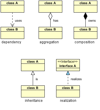
Now for the lines that connect the boxes. In the last lesson, we focused on the concepts behind association, aggregation, and composition. Now, we'll add two more essential relationships—inheritance and realization (implementation)—and learn the precise notation for all of them.
Association, Aggregation, and Composition
As a quick refresher:
- Association: A "uses-a" relationship between independent objects.
- Aggregation: A "has-a" relationship where the part can exist without the whole.
- Composition: A "part-of" relationship where the part cannot exist without the whole.
Inheritance and Realization
Two new, crucial relationships are:
- Inheritance (or Generalization): This is the classic "is-a" relationship (e.g., a
Caris aVehicle). The subclass inherits attributes and methods from the superclass. - Realization (or Implementation): This is used when a class "implements" an interface. It signifies a contract where the class promises to provide the functionality defined in the interface.
This image provides a clear, concise summary of the notation for these key relationships.
To see these explained with examples, let's return to the video.
Basics of LLD | UML Diagram in detail | Association Vs Aggregation Vs Composition | VERY imp!!
This next segment covers the notation for our relationships. It will solidify the concepts from our last lesson and introduce the notation for inheritance and interfaces.
Watch from 08:07 to 27:12. The video will first review Association, Aggregation, and Composition, focusing on their visual notation. Then, it will introduce: Inheritance: The solid line with a hollow, triangular arrow pointing to the superclass. Interfaces: How to label an interface (<<interface>> or italics) and the dashed line with a hollow, triangular arrow used for implementation.
3. Specifying Multiplicity
A critical part of defining relationships is specifying multiplicity—the number of instances of one class that can be related to a single instance of another. For example, a Customer can have many Orders, but an Order belongs to exactly one Customer.
UML has a simple notation for this:
| Multiplicity | Meaning |
|---|---|
1 |
Exactly one |
* |
Zero or more |
0..1 |
Zero or one (optional) |
1..* |
One or more |
m..n |
From m to n instances (e.g., 2..4) |
Multiplicity is shown near the end of the association line, on the side of the class it applies to.
The Lucid Software channel has a very quick and clear explanation of multiplicity with some easy-to-understand examples.
Watch from 08:29 to 09:42. Focus on how the different numerical notations (1, *, 1..*) are used to add constraints to the relationships.
4. A Complete Example
We've learned about the class box, the relationship lines, and multiplicity. Now, let's see how they all come together to describe a system.
Below is a comprehensive UML class diagram that models a system with people, pets, and addresses. It's an excellent example because it uses almost every concept we've discussed.

Let's break down the relationships shown in this diagram:
- Inheritance:
DogandCatboth inherit from theAnimalclass (which is abstract, noted by italics). This is the "is-a" relationship.Dogis anAnimal,Catis anAnimal. - Realization:
DogandCatboth implement thePetinterface. They fulfill the "pet" contract. - Composition: A
Personhas a strong "part-of" relationship with anAddress. The diagram implies that anAddresscannot exist without aPerson. If thePersonrecord is deleted, theirAddressis too. This is shown with the filled diamond. - Aggregation: A
Personhas a "has-a" relationship withPet. A person can own pets, but the pets can exist independently. This is shown with the hollow diamond. - Association: A
Personhas an association withPhone. This is a "uses-a" relationship. ThePersonandPhonehave independent lifecycles. This is shown with a simple line. - Dependency: The
Phoneclass "uses" thePhoneTypeenumeration. This isn't a structural "has-a" relationship but rather a dependency wherePhoneneedsPhoneTypeto function. This is shown with the dashed arrow.
This example brilliantly illustrates how different notations work together to tell a detailed story about the system's structure.
Test your understanding!
Let's return to the Parking Lot system design. In the last lesson, we identified the following relationships:
ParkingLothas a Composition relationship withLevel.Levelhas a Composition relationship withParkingSpot.ParkingSpothas an Aggregation or Association withVehicle.
Your task: Draw a basic UML class diagram for the ParkingLot and Level classes. Include:
- Class boxes for
ParkingLotandLevel. - The correct relationship line (Composition) between them.
- Appropriate multiplicity. (A
ParkingLothas one or moreLevels; aLevelbelongs to exactly oneParkingLot). - Add at least one attribute to each class (e.g.,
id: StringforParkingLot,floorNumber: intforLevel). - Add at least one method to
ParkingLot(e.g.,+addLevel(level: Level): void).
Don't worry about drawing a perfect diagram. Sketch it on paper or in your head and then check the answer.
Show answer
Here is what a simple diagram for this would look like:
+----------------+       1..*       +---------------+
|   ParkingLot   |<>----------------|     Level     |
+----------------+                  +---------------+
| - id: String   |                  | - floorNumber: int |
+----------------+                  +---------------+
| + addLevel(...): void |                  |               |
+----------------+                  +---------------+
Explanation:
- Classes: We have two boxes, one for
ParkingLotand one forLevel. - Attributes: Each class has a private attribute defined.
- Method:
ParkingLothas a public method. - Relationship: The line connecting them has a filled diamond (
<>) on theParkingLotside, signifying thatParkingLotis the "whole" in a Composition relationship. - Multiplicity:
- The
1next to theParkingLotdiamond indicates aLevelbelongs to exactly oneParkingLot. - The
1..*on theLevelside indicates aParkingLotis composed of one or moreLevels.
- The
Conclusion
Great job! You are now equipped with the essential vocabulary and grammar of UML class diagrams. This is a vital skill that moves you from simply thinking about code to designing and communicating a system's structure professionally.
Key Takeaways:
- Class Box: Consists of three parts: Name, Attributes, and Operations, with specific syntax for visibility, types, and parameters.
- Relationship Lines: Each relationship type (Association, Aggregation, Composition, Inheritance, Realization, Dependency) has a unique notation (lines, arrows, and diamonds).
- Multiplicity is Key: Use numerical notations (
1,*,1..*) to define the rules and constraints of your relationships. - UML is a Communication Tool: Its primary purpose in an interview is to help you articulate your design choices clearly and unambiguously.
In our next lesson, we will move from describing a design to improving it. We will begin to incorporate relevant design patterns to solve common design problems. The UML diagrams you learned to create today will be our canvas for visualizing and applying these powerful patterns.