
Hello, and welcome to the first module. This course begins with the professional context in which PSS®E and PSCAD studies are actually used: an interconnection request is not simply a simulation task. It is a controlled decision process that progressively turns a proposed solar plant, BESS, hybrid facility, or large load into an electrically defined, contractually committed, and model-verified grid connection.
Your ETAP work already provides useful foundations: power flow, fault duty, and protection coordination are familiar study categories. The change at transmission-interconnection scale is that those analyses sit inside a multi-party process. Case assumptions, project data, model versions, study scope, and findings must remain traceable because they influence queue position, required upgrades, agreements, construction, and ultimately permission to energize or synchronize.
By the end of this lesson, you should be able to map the major stages from early site screening through model acceptance, identify who acts at each stage, and recognize the deliverables that an interconnection engineer must create, review, or preserve.
The lifecycle: a decision process, not a single study
The FERC image below gives a useful high-level five-stage view: preparation, request, studies, agreement, and commercial operation. In practice, model development and acceptance are not isolated at the end. They begin early as preliminary data, become increasingly detailed during studies, and culminate in verification of the as-built facility.
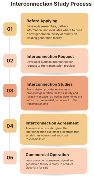
For a transmission-connected U.S. generator, the lifecycle can be understood as seven engineering-and-commercial gates:
| Stage | Core question | Principal technical deliverables |
|---|---|---|
| 1. Site screening | Is this location plausibly connectable and commercially viable? | Candidate POIs, preliminary one-line, capacity and voltage screening, preliminary fault-strength review, site ranking |
| 2. Interconnection request and validation | Is the project sufficiently defined and complete to enter the formal process? | Application forms, site-control evidence, requested MW, POI, deposits, schedule, initial technical data |
| 3. Cluster or system-impact studies | What reliability impacts and network upgrades result under defined study assumptions? | Study scope, base-case assumptions, power-flow and contingency results, short-circuit and stability findings, upgrade lists |
| 4. Facilities study and agreement | What specifically will be built, who pays, and under what conditions? | Detailed facility design and cost estimate, fault-duty assessment, agreement appendices, financial security |
| 5. Detailed engineering and construction | Does the physical plant match the approved electrical design? | Issued-for-construction one-lines, relay and meter designs, protection settings, telemetry and commissioning plans |
| 6. Commissioning and energization or synchronization | Can the facility be connected and operated without violating requirements? | Test records, operating procedures, final settings, metering and communications evidence, energization or synchronization approvals |
| 7. Model acceptance and continuing compliance | Do submitted models represent the facility that was actually built and tested? | As-built steady-state, short-circuit, RMS dynamic, and possibly EMT models; model-quality-test results; simulation files; verification reports |
The formal names and sequence differ among ERCOT, SPP, WECC-area transmission providers, and individual utilities. A study title is therefore not enough to tell you what has been done. Always determine:
- Which tariff or procedure governs the request?
- What is the project type? Generator, storage resource, solar-plus-BESS, load, or a hybrid configuration.
- What is the electrical connection? Transmission-connected, distribution-connected, or behind another customer’s facilities.
- What study phase and case revision are being discussed?
- Which deliverable is preliminary, final, or contractually binding?
A preliminary screening result can make a site look attractive without establishing a right to interconnect. Conversely, a completed facilities study may identify a technically feasible connection but with a cost or schedule that changes the project’s economics.
Stage 1: screen sites before entering a queue
Early screening is the developer’s decision-support work. It is usually performed before a formal request and often uses public transmission maps, available planning information, utility discussions, and appropriately authorized models or datasets.
For a 300 MW solar-plus-BESS project, a screening study might compare three candidate POIs. The engineer asks whether each candidate can plausibly support the proposed export, import during BESS charging, voltage-control range, contingencies, and expected project schedule. For a data center, the emphasis changes: peak demand, staged energization, load ramp, backup supply, voltage performance, short-circuit duty, and reliability of supply become central.
At this stage, avoid claiming “available capacity” as though it were a firm quantity. A lightly loaded line in one public base case does not prove that a proposed 300 MW project can interconnect without upgrades. Its loading may change with:
- seasonal load levels;
- renewable dispatch assumptions;
- generation retirement and additions;
- planned transmission expansion;
- N-1 contingencies;
- other queued projects;
- voltage or stability limitations that do not appear in a simple thermal screen.
A good site-screening package has a transparent, conditional conclusion:
Candidate B ranks highest under the stated public-data assumptions because it has lower preliminary thermal sensitivity and stronger fault level than Candidates A and C. The conclusion is not an interconnection-rights determination and must be re-evaluated against the applicable queue-study base cases and contingencies.
The central stakeholders are the developer or interconnection customer, the owner’s engineering team, land and permitting teams, and—often informally at this point—the prospective transmission owner or utility. The ISO/RTO may not yet have a formal active case, but its published procedures already shape the development strategy.
Stage 2: convert a proposed project into a valid request
A formal interconnection request fixes a project’s identity for process purposes: its location, requested capability, POI, schedule, and technical configuration. The applicant is usually called the Interconnection Customer in FERC-jurisdictional processes. ERCOT uses the term Interconnecting Entity (IE) in its generator process.
The request is not clerical paperwork. Its one-line diagram and technical data become the initial statement of what engineers will model. If the MW rating, POI, gen-tie route, transformer design, BESS charging capability, or commercial-operation date changes materially later, prior study conclusions may no longer apply.
In SPP’s generator-interconnection process, a complete request includes application materials, deposits and financial security, reasonable site control including gen-tie right-of-way requirements, and project data. Its Appendix 3 attachments call for items such as the POI, requested injection capability, generating-facility configuration, one-line diagram, schedule, and relevant equipment characteristics. Validation is distinct from model compatibility: an administratively complete request can still require correction if its models cannot run in the required study environment.
Guidelines for the SPP GIP Process and Business Practices
Read SPP’s practical overview of generator-request validation and its two-phase DISIS study. This is a concrete example of how a cluster process turns a proposed plant into a study-ready request.
In Section 1, “Generator Interconnection Request,” read the subsection “1.1 Application Process.” Start with the explanation that the current tariff requires a full Generator Interconnection Request and continue through the detailed Attachment A, B, and C information lists, ending at the statement that SPP will not rebuild an application from prior requests. Focus on the application data: distinguish commercial commitments such as site control and deposits from electrical information such as the one-line and equipment data. Then read subsection “1.2.1 Definitive Interconnection System Impact Study Queue (DISIS).” Review the study overview. Notice the split between Phase One power-flow/SCR work and Phase Two short-circuit and stability work.
The request-stage stakeholders
| Stakeholder | Main responsibility at this point |
|---|---|
| Interconnection Customer / developer | Defines the project, provides data, controls the site, funds required deposits, and responds to deficiencies |
| ISO/RTO or transmission provider | Administers the process, validates the request, assigns a queue identifier, and coordinates study activity |
| Transmission owner (TO) or transmission service provider (TSP) | Evaluates facilities it owns and may lead or participate in studies |
| Distribution utility, where applicable | Evaluates distribution-connected portions and provides feasibility or study information |
| OEMs and plant-control vendors | Supply equipment data, dynamic models, control settings, and sometimes EMT models |
| Owner’s engineer or consultant | Checks data consistency, performs independent sensitivities where permitted, and interprets results for the developer |
| Legal, commercial, land, and finance teams | Maintain site control, agreements, deposits, milestones, and project commitments |
For large-load interconnection, the labels and forms differ, but the discipline is the same. The applicant must describe not merely a peak MW number, but a credible electrical behavior: demand growth, energization blocks, power factor or reactive equipment, harmonic or motor-load characteristics if relevant, backup generation, and operating flexibility. A data center with a nominal 500 MW peak load is not a complete model until its staged loading, load composition, controls, and reliability arrangements have been specified.
Stage 3: study the project under defined assumptions
Once a request is accepted, the process moves from a proposed development into formal system analysis. The exact study sequence varies:
- SPP: cluster studies use the Definitive Interconnection System Impact Study, commonly divided into Phase One and Phase Two, then an Interconnection Facilities Study.
- ERCOT large-generator process: a high-level Security Screening Study may precede a Full Interconnection Study (FIS).
- Other regions: names such as feasibility study, system impact study, and facilities study are common, but the governing tariff and study agreement define their meaning.
Do not equate study names across regions. Instead, examine the scope: the network model, project assumptions, contingencies, performance criteria, analysis types, and decision point after the report.
At this stage, the owner’s engineering role becomes particularly important. You should be able to answer:
- What changed between the provided base case and the study case?
- Is the project modeled at the correct bus, voltage, MVA base, MW dispatch, and reactive-control mode?
- How is BESS charging represented?
- Which contingencies produce a violation?
- Is the violation pre-existing, newly created, or materially worsened by the project?
- Is an identified upgrade physically required for the interconnection, or does it depend on a contestable assumption, queue composition, or operating condition?
Study types are complementary
A full interconnection assessment normally combines multiple technical lenses:
| Analysis | Primary question | Typical outputs |
|---|---|---|
| Steady-state AC power flow | Are voltages, flows, transformer taps, and reactive limits acceptable in normal and contingency conditions? | Thermal loading, bus voltages, reactive reserve, N-1 results, transfer limits |
| Short-circuit analysis | Does the project increase fault duty beyond equipment ratings, and what grid strength exists at the POI? | Fault current, fault MVA, breaker-duty impacts, SCR or related screening metrics |
| RMS dynamic or transient stability | Does the project and system remain stable following credible disturbances? | Voltage and frequency traces, oscillations, stability findings, ride-through and recovery behavior |
| EMT analysis, when required | Are fast converter controls, protection interactions, resonance, or phase-angle effects adequately represented? | Sub-cycle waveforms, control and protection response, harmonic or resonance evidence |
| Facilities analysis | What physical equipment must be installed or modified? | Substation configuration, breakers, relays, line work, construction scope, cost estimate, schedule |
The later PSS®E and PSCAD modules will develop these distinctions in detail. For now, the key is that a single green power-flow result never establishes complete interconnection feasibility. It does not answer whether breaker duty is exceeded, whether an inverter-based plant recovers after a fault, or whether a detailed physical connection can be built on the proposed schedule.
In ERCOT’s large-generator framework, the Security Screening Study is a high-level steady-state review intended to indicate the suitability of the proposed POI and MW level before deeper work. The FIS can include steady-state, stability, short-circuit, facility, and other relevant studies. Its stated purpose is reliability and identifying facilities needed for interconnection—not guaranteeing unconstrained market deliverability or eliminating all future curtailment risk.
Use these ERCOT Planning Guide excerpts to see how an initial screen leads to a scoped, multi-discipline Full Interconnection Study. Treat this as a process example and verify the current effective ERCOT documents before applying deadlines or exact requirements to a live project.
First, in Section “5.3.1 Security Screening Study,” read from the screening-study purpose. Focus on what a preliminary report can tell a developer and, equally, what it does not commit ERCOT or a transmission provider to do. Next, in “5.3.2 Full Interconnection Study,” read the opening description and the subsection “5.3.2.2 Full Interconnection Study Scoping Process.” In particular, study the role of simulations, then follow the kickoff and study-agreement discussion. Identify the study scope, assumptions, timetable, costs, and payment schedule as deliverables that must be agreed rather than inferred.
The study agreement is an engineering control document
A study agreement or equivalent scope document is where engineering uncertainty becomes managed work. It should identify, at minimum:
- project configuration, MW/MVA capability, POI, and in-service date;
- study years, seasons, load levels, dispatch assumptions, and queue assumptions;
- base-case and dynamic-data versions;
- applicable criteria and contingency sets;
- steady-state, short-circuit, dynamic, EMT, or special-study scope;
- responsibilities of the ISO/RTO, TO/TSP, developer, OEM, and consultants;
- cost, schedule, review periods, and decision points;
- data confidentiality and permitted model use.
A technically capable engineer reads this document before opening PSS®E. Otherwise, it is easy to produce a correct simulation of the wrong question.
Stage 4: facilities, cost allocation, and the interconnection agreement
The system-impact phase identifies what may be needed. The facilities phase translates that conclusion into buildable equipment and more refined cost and schedule information.
For example, a study may conclude that a solar-plus-BESS project requires a new breaker-and-a-half bay, a 345/34.5 kV transformer connection, protection and communications changes, reconductoring, and a remote network upgrade. The facilities analysis must establish details sufficient for procurement and construction planning, while also checking whether the new configuration changes short-circuit duty at existing breakers.
The interconnection agreement is the contractual bridge between analysis and construction. In SPP, the Generator Interconnection Agreement (GIA) enables the physical connection of the generator to the transmission grid. It is separate from arrangements for transmission service. This distinction matters: physical interconnection does not automatically establish all rights needed to schedule or deliver energy under a separate transmission-service framework.
Guidelines for the SPP GIP Process and Business Practices
This final SPP reading connects the study findings to buildable facilities and an executed Generator Interconnection Agreement.
Read Section “7 Interconnection Facilities Study (IFS),” especially the two IFS analyses. Then read Section “9 Generator Interconnection Agreement (GIA)” through the paragraph explaining the initial payment. Focus on the distinction between a study estimate, financial security, a physical-interconnection agreement, and separately arranged transmission service.
For independent technical review, this is often the point at which the developer asks whether a lower-cost alternative is credible. The proper question is not “Can we simply reject the upgrade?” It is:
Under the same applicable criteria and suitably conservative assumptions, can another topology, operating limit, project configuration, phased solution, protection scheme, or transmission alternative address the identified reliability issue with acceptable residual risk?
A defensible challenge preserves the original case and result, isolates the project’s incremental contribution, documents the alternative, and acknowledges limitations. Those skills are developed later in the SPP sensitivity and upgrade-challenge modules.
Stage 5 through 7: construct, commission, and establish that the models match reality
The final phases bring a crucial distinction into view:
- A planning model is the best available representation used to assess a proposed facility.
- An as-built model represents the actual equipment, settings, controls, and electrical configuration installed in the field.
- Model acceptance is the process by which the applicable entities review whether those submitted models and supporting evidence are usable and sufficiently representative for their required purpose.
For an inverter-based solar or BESS facility, the models are usually a chain rather than one file. They may include:
- a steady-state power-flow representation;
- positive-sequence RMS dynamic models for the converter, electrical controls, plant power controller, and protection;
- model parameter files, often including a PSS®E
.dyrfile; - test cases, event definitions, output channels, and simulation files;
- an EMT model when the region, transmission provider, or study scope requires it;
- documentation that identifies model versions, assumptions, settings, and known limitations.
The model must align with the physical plant at defined measurement points, particularly the POI. A plant that appears correct at inverter terminals can still be misrepresented at the POI if the collector equivalent, GSU transformer, reactive equipment, plant controller, measurement scaling, or remote-voltage-control configuration is wrong.
ERCOT’s published generator procedures illustrate the seriousness of this late-stage checkpoint. For applicable inverter-based resources, the project submits as-built dynamic models, documentation of differences from the models used in the quarterly stability assessment, model-quality-test overlays, and associated simulation files before commissioning; subsequent updates and a verification report follow after commissioning. The important general lesson is that model work is a commissioning deliverable, not merely a consultant’s study artifact.
Read this excerpt to connect commissioning approval with as-built model evidence and later model-maintenance obligations for inverter-based resources.
In Section “5.5 Generator Commissioning and Continuing Operations,” first scan the conditions listed for Initial Energization, Initial Synchronization, and commercial operation. Then read the as built model submission. Focus on the required comparison between the as-built model and the earlier planning model, plus the role of model-quality-test overlays and simulation files.
A practical deliverable map for an interconnection engineer
The following checklist summarizes what you should expect to manage across the lifecycle.
| Lifecycle point | Deliverable you may prepare or review | Why it matters |
|---|---|---|
| Screening | Candidate-POI comparison and assumptions register | Prevents informal conclusions from being mistaken for queue-study results |
| Request | One-line, coordinates, requested MW, project schedule, site-control support, initial equipment data | Defines the project that will enter the formal process |
| Study kickoff | Study-scope review and data transmittal log | Makes assumptions, responsibilities, and missing data visible |
| Study execution | Traceable model package, case-modification log, results tables, plots, issue tracker | Allows findings to be reproduced and challenged responsibly |
| Report review | Comment matrix tied to contingencies, criteria, cases, and upgrade rationale | Turns a vague concern into an actionable technical question |
| Facilities/agreement | Facility-scope review, cost and schedule comparison, agreement appendix review | Connects analytical results to physical and financial commitments |
| Commissioning | Final one-lines, settings records, test evidence, telemetry and protection documentation | Shows that the installed project meets operational conditions |
| Model acceptance | As-built model package, MQT evidence, overlays, simulation files, model-difference register | Establishes a supportable representation for future planning and operations |
For a large load, substitute initial energization for generator synchronization where appropriate, and place special weight on the load commissioning plan, staged demand profile, dynamic load representation, and required reactive-support arrangements. The underlying workflow remains: define the project, study its system impact, agree on the connection, construct it, and demonstrate that the model and the physical facility agree closely enough for reliable planning and operation.
A disciplined way to use this map on real projects
When you receive an interconnection package, begin by building a one-page lifecycle register rather than immediately reviewing PSS®E files. Include these columns:
- Current process stage
- Governing procedure and revision
- Project definition used in the current study
- Responsible party
- Required input or deliverable
- Status and date
- Open technical risk
- Effect if the item changes
This register separates three issues that are often blurred together:
- Process status: Has the project passed a formal gate?
- Technical conclusion: What did a defined study demonstrate?
- Commercial commitment: What has been agreed, funded, or made subject to security?
That separation will be especially valuable later when you reproduce a utility or SPP result, perform sensitivity studies, and assess whether an upgrade is driven by your project, by baseline conditions, or by an interaction among clustered projects.
Key takeaways
A U.S. interconnection proceeds through linked decisions: screen a site, submit a valid and sufficiently defined request, study system impacts, develop facilities and an agreement, construct and commission the plant, then verify that the operational models represent what was built.
The principal stakeholders are the interconnection customer, ISO/RTO or transmission provider, transmission owner, distribution provider where relevant, OEMs, consultants, and commercial and regulatory teams. Their responsibilities overlap, but the developer remains responsible for supplying complete, consistent project information and for responding when data or design changes.
Finally, studies do not themselves grant interconnection rights, and a signed agreement does not eliminate technical obligations. Model acceptance is an ongoing reliability responsibility, particularly for inverter-based resources whose controls, protection, and plant power controller determine POI behavior.
Next, we will distinguish the authority of FERC process documents, NERC standards, regional criteria, ISO/RTO guides, transmission-owner requirements, and project-specific agreements—so that, when a requirement appears in a study scope or model request, you can identify what makes it binding and how it applies.
Can't find a good explanation? Sign up and we'll make it for you
Sign up