
Hello. In the previous lesson, you estimated cooling time from wall thickness and thermal assumptions. That calculation showed why unnecessary thick sections raise cycle time. This lesson examines the other major force acting during molding: the pressure of the polymer trying to push the mold halves apart.
You will calculate an initial mold clamp-force requirement from the part’s projected area, the number of cavities, an estimated cavity pressure, and a declared safety margin. This is an early machine-screening calculation, not a substitute for a molder’s clamp-force analysis, mold-flow result, or cavity-pressure measurement.
The physical problem: pressure creates separating force
During filling and packing, molten polymer exerts pressure on the cavity surfaces. The component of that pressure acting normal to the mold’s opening direction tends to separate the mold at its parting line. The injection-molding machine supplies an opposing clamp force to keep the mold closed.
If available clamp force is insufficient, the mold may open by a very small amount and create flash: unwanted plastic forced out at the parting line, inserts, shutoffs, or side-action interfaces.
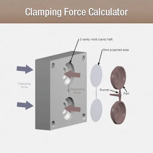
The relevant area is not the three-dimensional surface area of the part. It is its projected area: the two-dimensional “shadow” seen looking along the clamp or mold-opening direction.
For a conventional mold with identical cavities:
where:
| Symbol | Meaning |
|---|---|
| Total pressure-bearing projected area for the shot | |
| Number of cavities | |
| Projected area of one molded part | |
| Projected area of runners, sprue, gates, and cold wells where these lie at the relevant separating plane |
The nominal mold-separating force is then:
Finally, apply a justified safety factor:
Here, is a multiplier such as , , or , not an added number of tonnes.
A useful interpretation is:
- Projected area tells you how much pressure-bearing “footprint” the mold has.
- Cavity pressure tells you the intensity of the opening load.
- Cavity count multiplies the part footprint.
- Safety factor acknowledges uncertainty and normal process variation.
Read the practical calculation workflow
The following guide gives a concise industry-style walkthrough. Its pressure factors are suitable only as initial screening values; a material supplier, molder, cavity-pressure data, or mold-flow study should replace them as the project matures.
Read Delaney Manufacturing’s guide to reinforce the definition of projected area, the importance of including the feed system, and the distinction between a tonnage estimate and complete machine selection.
In “What Is Projected Surface Area in Injection Molding?”, read from the projected-area explanation. Focus on why the runner system is included and why a part’s mass is not an input to clamp-force calculation. Then read “How Projected Area and Pressure Create Clamping Force” from the pressure calculation discussion. Note the warning that the pressure estimate must be specific to the resin and flow geometry. In “Worked Example: Estimating Injection Molding Tonnage,” follow the worked walkthrough. Finish with the “Factors That Change the Required Tonnage” section, especially the selection factors.
Define projected area correctly
For an early automotive design calculation, you need a projected area that is conservative enough to screen molding-machine capacity, but traceable enough that a toolmaker can later refine it.
The mold-opening direction controls the view
Projected area must be measured perpendicular to the mold-opening direction. For a simple two-plate mold, this is normally perpendicular to the parting plane.
For a rectangular cover whose plan-view silhouette is , a conservative envelope calculation is:
Its depth does not directly increase projected area. A deep box and a shallow lid with the same opening-direction silhouette can have similar clamp-force requirements, assuming comparable pressure.
For a complex enclosure, carrier, or HVAC outlet, use CAD to create or measure the projected silhouette normal to the proposed tooling axis. At this stage, retain the following in the calculation record:
- CAD document, version, and part revision.
- Proposed tooling axis or main pull direction.
- Projected-area sketch, drawing view, or exported measurement.
- Whether the area is an exact cavity projection or a conservative bounding estimate.
- Runner-system assumption: cold runner, hot runner, or not yet defined.
Include the full pressure-bearing shot footprint
For a multi-cavity cold-runner mold, the appropriate early estimate is:
A common error is to multiply the part area by cavity count and omit a large cold-runner system. This can underpredict required clamp force, particularly for small parts arranged far apart in a multi-cavity tool.
A few practical boundaries matter:
| Item | Include in initial projected area? | Reason |
|---|---|---|
| Each molded part | Yes | Cavity pressure acts over its projected footprint |
| Cold runners, sprue, gates, cold wells | Usually yes | They are also filled and pressurized at the mold separation plane |
| Three-dimensional outer surface area | No | It is not the pressure-bearing projected footprint |
| Part mass | No | Mass affects shot size and cycle time, not clamp force directly |
| Wall thickness | Not directly | It changes filling resistance and therefore can change cavity pressure |
| Slides and lifters | Assess separately | They require their own force, shutoff, and locking review with the toolmaker |
With a hot-runner system, the projected feed-system contribution may be much smaller than with a cold runner. Do not simply set it to zero without confirming the proposed mold architecture.
Cavity pressure: use a design input, not injection-machine pressure
The pressure needed for a clamp-force calculation is the pressure acting within the cavity. It is not automatically the injection pressure displayed at the machine nozzle. Pressure is lost through the barrel, nozzle, sprue, runner, gate, and flow path; it is also nonuniform across the cavity during filling and packing.
For early work, label your input clearly as an estimated effective cavity pressure or design cavity pressure. As the design matures, replace the assumption with evidence.
A sensible evidence hierarchy is:
- A mold-flow result reporting predicted clamp force or cavity pressure for the actual geometry, material grade, gate design, and process window.
- Measured cavity-pressure data from a similar validated tool and material grade.
- A molding supplier’s documented estimate based on geometry and process experience.
- A transparent initial screening estimate, marked as low-confidence and subject to review.
Do not treat cavity pressure as a universal material-family constant. It is affected by:
- polymer grade and moisture condition;
- filler level and fiber content;
- melt temperature and mold temperature;
- wall thickness and flow length;
- gate type, size, and position;
- fill speed, packing profile, and transfer point;
- venting quality;
- number and balance of cavities.
For example, a glass-filled PA66 enclosure may require a higher pressure than an unfilled PP component of the same silhouette, but the actual result still depends strongly on gate location, wall thickness, and flow length.
Use consistent units
The most defensible version of the equation uses SI units:
with pressure in pascals, area in square metres, and force in newtons.
In molding practice, projected area is often recorded in , cavity pressure in bar, and clamp force in either kilonewtons or metric tonne-force. The following conversions are useful:
where means metric tonne-force.
The form is preferable in a controlled calculation because it avoids ambiguity. A machine described commercially as a “300-ton press” may use a different ton convention depending on region and supplier. Record both the selected machine’s rated clamp force in and the supplier’s stated tonnage convention.
Worked example: two-cavity automotive component
Consider an assumption-based early mold concept for a two-cavity molded automotive component. The values are illustrative, not production data for a Rivian-built Amazon EDV component.
| Input | Value | Rationale |
|---|---|---|
| Projected area per part, | CAD-measured cavity silhouette | |
| Cavity count, | Proposed two-cavity production tool | |
| Runner and gate projected area, | Assumed cold-runner layout | |
| Design cavity pressure, | Initial molder or simulation screening input | |
| Safety factor, | Early engineering-plastic tool concept with pressure uncertainty |
1. Calculate total projected area
2. Calculate nominal separating force
First, calculate the force before safety margin:
This is approximately:
3. Apply the safety factor
The initial clamp-force screen is therefore , or about .
A machine with a rated clamp force of , if available, would be a plausible first candidate because it exceeds the calculated requirement. It is not yet an approved machine selection.
The molder must still verify:
- mold overall dimensions, platen spacing, tie-bar clearance, and daylight;
- shot capacity and recommended shot-size operating range;
- injection-pressure and injection-rate capability;
- ejector stroke and ejector force;
- mold weight and handling constraints;
- temperature-control circuits and available cooling capacity;
- process capability at the intended cycle time.
A machine with an unsuitable injection unit or inadequate tie-bar spacing remains the wrong machine.
Choosing a safety margin deliberately
The safety factor addresses uncertainty; it should not compensate for an unknown or poorly defined process. Use a larger margin when the pressure estimate is less certain, but make the reason explicit.
A practical early guideline is:
| Situation | Illustrative safety factor | Why |
|---|---|---|
| Validated process with measured cavity-pressure evidence | Lower uncertainty and stable process window | |
| Typical early engineering-plastic concept | Allows for normal uncertainty, pressure variation, and initial process development | |
| Glass-filled, thin-wall, tight-tolerance, or poorly characterized concept | to | Higher risk of pressure peaks and uncertainty in filling behavior |
A safety factor of means that the selected clamp capacity is 20 percent above the calculated nominal force. Do not apply two separate margins without documenting them. For example, if a supplier’s mold-flow report already states a recommended machine clamp force including margin, adding another would double-count uncertainty.
Equally, avoid using excess clamp force as the solution to a process problem. If the mold flashes because fill pressure is unexpectedly high, investigate gate restriction, excessive packing, poor venting, mold mismatch, and actual cavity-pressure data. Increasing tonnage alone can conceal a tooling or process-control problem.
Turn the estimate into a controlled design record
For the ECU housing, door carrier, and HVAC outlet projects, create a Clamp Force Screening Record alongside the cooling-time record from the previous lesson.
A concise controlled record should contain:
| Field | Example content |
|---|---|
| Record ID | MFG-CLAMP-HVAC-001 |
| Part and revision | Driver-zone HVAC outlet housing, concept revision A |
| Mold concept | Two-cavity, cold runner, proposed main pull direction |
| CAD evidence | Onshape document/version and projected-area sketch or drawing |
| Area inputs | Part projected area, cavity count, runner area, total shot projected area |
| Pressure input | Value, units, source, confidence, and whether it is measured, simulated, supplier-estimated, or assumed |
| Safety factor | Value and risk-based justification |
| Result | Separating force and required clamp force in and |
| Machine screen | Candidate machine capacity and open compatibility checks |
| Risks | Flash, cavity imbalance, tool deflection, runner growth, side-action loading, or pressure uncertainty |
| Verification | Mold-flow study, supplier review, cavity-pressure measurement, tool trial |
| Maturity and change link | Draft, supplier-reviewed, trial-correlated, superseded; plus ECO reference if revised |
In an ENOVIA-controlled environment, this record would link to the CAD revision, material specification, mold-flow evidence, DFMEA, manufacturing feasibility review, and later tooling change. In the Onshape-based workflow, preserve equivalent traceability through document versions, release notes, a controlled spreadsheet or template, and a project change register.
Key takeaways
Required clamp force is the pressure-induced mold-opening force multiplied by a justified safety factor.
- Measure projected area as the two-dimensional pressure-bearing footprint viewed along the mold-opening direction.
- For identical cavities, calculate total shot projected area from part area times cavity count, then add the relevant runner and feed-system area.
- Use an estimated cavity pressure, not the machine’s displayed nozzle pressure.
- Keep units explicit. Recording force in reduces ambiguity during machine selection.
- A safety factor is a controlled response to uncertainty, not a substitute for mold-flow work, process development, or tooling correction.
- Adequate tonnage is only one machine-selection criterion; shot size, mold envelope, injection unit, daylight, ejection, and cooling capacity also matter.
Next, you will return to part geometry and use wall-thickness selection plus gradual transitions to balance structural function, molding quality, cooling time, and sink risk.
Can't find a good explanation? Sign up and we'll make it for you
Sign up